Table of Contents
- Why RF Shielding Matters for Accurate Testing
- Shielding Effectiveness and Isolation Levels in an RF Shield Box
- Leakage Points and Mechanical Design
- Internal Absorbers and Signal Control
- Frequency Range and Application Needs
- Interface Design and Connectivity
- Build Quality and Materials
- Automation and Repeatability
- Thermal Management
- Size and Performance Balance
- Choosing the Right RF Shield Box for Reliable Testing
- Frequently Asked Questions
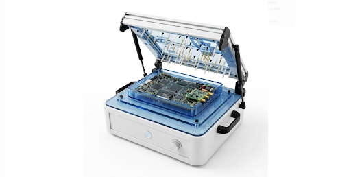
In wireless testing, results must be accurate, repeatable, and free from external interference. However, external electromagnetic interference (EMI) can impact measurements at any time. Because of this, engineers use RF shielding to control the test environment when working with an RF shield box.
An RF shield box attenuates unwanted signals and reduces noise from nearby sources. As a result, testing becomes more reliable and consistent. This is important during development, validation, and production testing.
At the same time, not every enclosure performs in the same way. Many small design details affect its shielding effectiveness and isolation performance. Therefore, understanding RF shield box performance factors helps engineers make better design and selection decisions.
Key Takeaways
- RF shielding helps maintain accurate and repeatable testing by attenuating external electromagnetic interference, so results remain reliable.
- Strong isolation in an RF shield box ensures stable measurements by preventing unwanted signals from entering or escaping the enclosure.
- Leakage points can significantly reduce performance, as even small gaps or seams allow signals to interfere with testing.
- Internal absorbers help control reflections and reduce standing waves, improving measurement consistency.
- Good interface design, including proper filtering and feedthroughs, prevents leakage through cables and connections.
- High build quality supports long-term performance by maintaining proper electrical contact and shielding integrity.
- Effective thermal management keeps test conditions stable, minimizing the impact of temperature on DUT performance and material properties.
Why RF Shielding Matters for Accurate Testing
Wireless devices operate in environments where multiple signals and sources of electromagnetic interference (EMI) are present. As a result, testing without proper shielding can lead to inaccurate or inconsistent results. Therefore, RF shielding is essential to minimize external interference.
A well-designed RF shielded test enclosure attenuates external signals and provides high isolation, improving measurement accuracy. This enables engineers to achieve stable, repeatable, and reliable test results, highlighting the importance of RF shielding in modern testing environments.
Shielding Effectiveness and Isolation Levels in an RF Shield Box
Shielding effectiveness (SE) indicates how well an RF shield box attenuates external electromagnetic signals. It is measured in decibels (dB), where higher values represent greater attenuation.
Isolation refers to the overall ability of the enclosure to prevent unwanted signals from entering or escaping. If isolation is insufficient, external interference can affect the test environment, leading to variations in measurement results.
Because of this, shielding effectiveness and isolation are among the most critical performance factors of an RF shield box.
Engineers should consider:
- Required attenuation level (dB)
- Performance across the operating frequency range
- Stability and repeatability during repeated tests
Leakage Points and Mechanical Design
Leakage points significantly reduce shielding performance, as even small gaps or discontinuities can allow electromagnetic signals to leak through or couple into the enclosure. Therefore, proper mechanical design is essential.
Common leakage areas include:
- Door edges (requiring RF gaskets)
- Panel joints and seams
- Cable entry points and feedthrough interfaces
If these areas are not properly sealed, external interference can enter the enclosure, leading to inaccurate and inconsistent test results. As a result, overall shielding effectiveness and isolation performance can degrade.
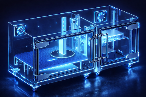
Internal Absorbers and Signal Control
Inside an RF enclosure, electromagnetic signals can reflect from internal metallic surfaces. These reflections can create standing waves and multipath effects, which may impact measurement accuracy. Therefore, RF absorbers are used.
Absorbers reduce reflections and help control the internal electromagnetic environment, improving measurement stability and consistency.
This is especially important in RF shield boxes and isolation chambers, where controlled and predictable signal behavior is required for accurate testing.
Frequency Range and Application Needs
Each wireless device operates within a specific frequency range, and the RF shield box must provide adequate shielding effectiveness across that range.
Shielding performance varies with frequency; higher frequencies are more sensitive to small leakage paths, while lower frequencies can be more difficult to attenuate due to longer wavelengths. If the enclosure does not perform consistently across the required frequency range, measurement results may become unreliable.
Therefore, selecting an RF shield box that meets the shielding requirements for the intended frequency range and application is essential.
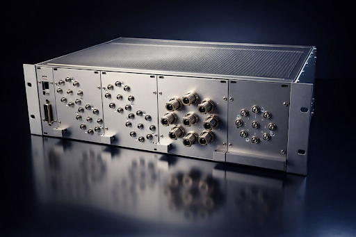
Interface Design and Connectivity
RF test systems require multiple connections, such as RF ports, USB, Ethernet, and power lines. However, each interface can act as a potential leakage path if not properly designed.
Therefore, interface design must preserve shielding integrity by minimizing signal leakage through connectors, cables, and feedthroughs. This is typically achieved using properly shielded connectors, filtered feedthroughs, and good grounding practices.
A well-designed RF shield box ensures that external connections do not degrade shielding effectiveness and isolation, making interface design a critical factor in overall RF shield box performance.
Build Quality and Materials
The materials used in an RF enclosure have a direct impact on its shielding performance. High-quality construction using conductive materials such as aluminum or steel provides better attenuation and longer service life.
Important factors include:
- High-conductivity materials and appropriate thickness
- Robust mechanical structure
- Proper sealing with good electrical continuity (e.g., RF gaskets)
Good construction quality helps maintain consistent shielding effectiveness over time by preventing degradation due to wear, corrosion, or mechanical stress. This is important for both fixed installations and portable RF shielded boxes used in varying environments.
Automation and Repeatability
In many RF test setups, measurements are automated to improve efficiency and consistency. Therefore, the RF shield box should be compatible with automation systems such as robotic handling or automated test equipment (ATE).
Automation helps increase test speed and reduces manual errors, resulting in more consistent and repeatable measurements.
Repeatability is critical in RF testing. Variations in factors such as DUT positioning, cable routing, or door closure can affect results. Therefore, stable mechanical design, precise positioning, and controlled operation are necessary to ensure consistent test conditions.
While automation does not directly improve shielding effectiveness, it plays a key role in maintaining reliable and repeatable test performance.
Thermal Management
Devices under test (DUTs) generate heat during operation, especially during RF testing. If this heat is not properly managed, it can lead to temperature-induced variations in device performance, affecting measurement accuracy.
Proper thermal management helps maintain stable test conditions by controlling temperature and preventing overheating. This ensures more consistent and reliable measurement results.
In RF shield boxes, thermal solutions such as fans or ventilation must be carefully designed to avoid introducing additional leakage paths, ensuring that shielding effectiveness is not compromised.
Size and Performance Balance
The size of an RF enclosure affects both usability and shielding performance. Larger enclosures provide more space for devices and test setups, but they are more challenging to shield effectively due to increased seams, joints, and potential leakage paths.
Smaller enclosures are generally easier to seal and maintain high shielding effectiveness, but they may limit the size of the device under test (DUT) and test configurations.
Engineers should consider factors such as DUT size, required isolation level, and available space when selecting an enclosure. Therefore, achieving the right balance between size and shielding performance is an important aspect of RF shield box design.
Choosing the Right RF Shield Box for Reliable Testing
Selecting the right RF shield box is critical because shielding performance directly affects measurement accuracy, repeatability, and consistency. Multiple factors, including mechanical design, materials, interface design, and thermal management, contribute to overall performance.
When choosing an RF shield box, engineers should consider key parameters such as shielding effectiveness (isolation level), leakage control, frequency range, and build quality. A well-designed enclosure provides a controlled electromagnetic environment, enabling accurate and repeatable test results.
This highlights the importance of RF shielding in ensuring reliable wireless testing.
Frequently Asked Questions
1. What is an RF shield box used for?
An RF shield box is used to attenuate external radio signals during testing. It creates a controlled environment where electromagnetic interference is minimized. This enables engineers to perform accurate and repeatable tests in both development and production environments.
2. Why is RF shielding important in testing?
RF shielding is important because external electromagnetic interference (EMI) can affect measurements. Even small levels of interference can introduce errors or variability. Therefore, shielding helps maintain stable and repeatable test conditions, allowing engineers to trust the measurement data.
3. What are the key RF shield box performance factors?
The key factors include shielding effectiveness (SE), leakage control, internal absorbers, interface design, and thermal stability. In addition, frequency range, build quality, and mechanical design also play important roles. Together, these factors ensure accurate and consistent RF testing.
4. How do leakage points affect RF enclosure testing?
Leakage points allow electromagnetic signals to leak into or out of the enclosure, reducing isolation and overall shielding performance. Common areas include doors, seams, joints, and cable entry points. Therefore, proper sealing using RF gaskets and well-designed interfaces is essential for accurate testing.
5. How do I choose the right RF shield box?
To choose the right RF shield box, consider factors such as frequency range, required shielding effectiveness (isolation level), device size, and interface/connectivity needs. In addition, evaluate build quality and compatibility with your test setup. This ensures reliable, accurate, and repeatable testing results.