Categories
Blogs

Test Equipment Integration: Bringing New Systems Into an Existing Production Line

Table of Contents

  1. Why Test Equipment Integration Matters in Modern Manufacturing
  2. Common Challenges When Introducing New Test Equipment
  3. Planning a Successful Test System Rollout
  4. Key Steps in Production Line Integration
  5. The Value of Automated System Integration
  6. Why System Integration Testing Is Essential Before Go-Live
  7. Working with Experienced Manufacturing Systems Integrators
  8. Key Takeaway
  9. Conclusion
  10. FAQs

Test Equipment Integration: Bringing New Systems Into an Existing Production Line

Key Takeaway

  • Production line integration works best as an ongoing engineering process rather than a one-time installation
  • Planning, validation, and commissioning each play a role in making sure a test system rollout supports steady production rather than interrupting it
  • Working with an experienced integrator such as Orbis Systems helps keep that process aligned with a facility’s current operations and future plans

Manufacturing teams rarely get the luxury of pausing a production line for long once new test equipment needs to go in. Whether the goal is expanding capacity, replacing aging systems, or preparing for a new product launch, production line integration calls for planning that keeps daily output steady while new hardware and software find their place. This is where a structured test system rollout matters. New equipment onboarding, when handled step by step, gives manufacturers a way to introduce updated RF systems without losing sight of quality or throughput.

Why Test Equipment Integration Matters in Modern Manufacturing

Products keep getting more complex, and testing requirements tend to follow that same curve. Adding new RF test equipment to a production floor that already has its own rhythm is not simply a matter of swapping one box for another. Software, fixtures, automation platforms, and communication interfaces all have to keep working together, and none of that can come at the expense of product quality.

Production line integration, done well, looks past the equipment itself. It starts with understanding how the current environment actually operates, checking where new systems will and will not fit, confirming performance, and making sure operators can pick up the new workflow without a steep learning curve.

Integrating RF systems into manufacturing through a structured, engineering-led process tends to cut down on avoidable delays while keeping production quality steady. It also sets up future production line upgrade work to go more smoothly, since the groundwork is already in place.

Common Challenges When Introducing New Test Equipment

No two manufacturing facilities look alike. Workflows, equipment configurations, and priorities all differ, so new equipment onboarding tends to surface its own engineering questions each time. A few of the more common ones include:

  • Getting existing automation software to work properly with new test equipment
  • Making sure instruments, fixtures, and manufacturing systems can actually communicate with one another
  • Holding to production schedules while installation and commissioning are underway
  • Confirming measurement accuracy before the line goes back into full production
  • Training operators on updated equipment and revised workflows
  • Keeping traceability and consistent test data intact throughout the process

Skipping ahead without addressing these points can slow down a test system rollout and add engineering effort that a bit of early planning would have avoided.

Ready to start planning your next equipment integration project?

Talk to an Orbis Systems engineer today.

Planning a Successful Test System Rollout

A solid test system rollout starts well before any equipment shows up on the floor. Early planning gives engineering teams room to work through technical requirements, flag potential risks, and shape an implementation approach that fits the existing manufacturing setup rather than fighting against it.

That stage usually begins with a look at production goals, available floor space, current automation systems, and the communication interfaces already in use. Engineers also consider how the new equipment is likely to interact with existing workflows and whether adjustments are needed before installation even begins.

Once planning is done, validation takes over. Factory Acceptance Testing, or FAT, confirms equipment meets specifications before it ships, and Site Acceptance Testing, or SAT, checks that everything still performs correctly once installed on site. These two stages give manufacturers a clearer picture of whether equipment is genuinely ready for a full production role.

A well-managed test system rollout also folds in commissioning, documentation, and operator preparation. Together, these pieces tend to make the move from installation to daily production noticeably smoother.

Key Steps in Production Line Integration

Production line integration works best as a structured sequence rather than a single installation event. Each stage builds on the last and contributes something to how the system performs over time. In practice, this process generally includes:

  • Reviewing production requirements alongside existing manufacturing infrastructure
  • Checking compatibility between new equipment and current automation systems
  • Installing hardware, fixtures, RF instruments, and other supporting components
  • Bringing software, communication interfaces, and automation controls online together
  • Running calibration, validation, FAT, and SAT
  • Completing commissioning before the system is cleared for production use

Working through these steps in order helps manufacturers manage new equipment onboarding without sacrificing production quality or taking on more operational risk than necessary. It also gives the facility a foundation that can support both current output and future production requirements.

The Value of Automated System Integration

As manufacturing environments become more connected, automated system integration is playing a bigger role in keeping production performance steady. Instead of running each piece of equipment on its own, integrated automation lets multiple systems share information and operate as part of one coordinated process, which tends to make workflows more consistent and cuts down on manual steps.

For RF manufacturing environments specifically, automation can also strengthen traceability by supporting consistent test execution and organized data collection. This makes it easier for engineering teams to monitor production performance while keeping documentation reliable throughout the process.

Automated system integration also leaves room for future growth. When integration is planned with expansion in mind from the outset, later production line upgrade projects often require fewer changes to workflows that already work well.

Why System Integration Testing Is Essential Before Go-Live

Getting new equipment installed is only part of the job. Before production resumes, engineering teams need to confirm that every system works correctly within the full manufacturing environment, and that is where system integration testing comes in.

This kind of testing checks whether hardware, software, communication interfaces, automation controls, and RF instruments function together the way they are supposed to. Rather than looking at each component in isolation, the focus shifts to how the complete system behaves under conditions that resemble real production.

Validation work at this stage typically covers communication checks, functional testing, calibration, performance verification, and an overall readiness assessment. These steps tend to catch issues while they are still easy to address, before they affect day-to-day manufacturing.

Thorough system integration testing gives manufacturers a clearer sense of whether production can start on stable, repeatable footing, lowering the odds of unexpected interruptions once the system goes live.

Working with Experienced Manufacturing Systems Integrators

Larger integration projects often bring together several engineering disciplines, manufacturing requirements, and stakeholders at once. Partnering with experienced manufacturing systems integrators helps keep those moving parts coordinated from start to finish.

That kind of engineering experience matters most when RF equipment is being integrated into an environment with its own established processes, where compatibility, automation, validation, and commissioning all need attention at the same time.

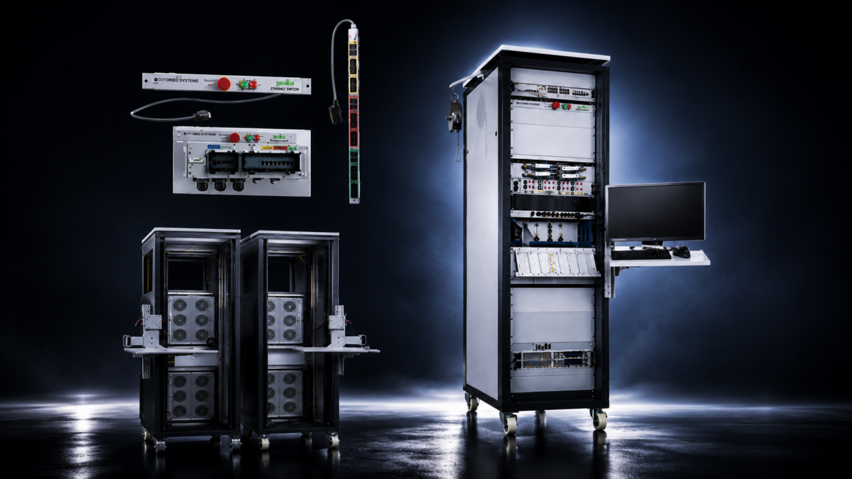
Orbis Systems works with manufacturers on engineering, test equipment integration, manufacturing integration, commissioning, and lifecycle support, drawing on RF, OTA, and 5G testing experience built up across telecom and electronics production environments. Their engineering teams bring together RF instruments, signal switching units, automation interfaces, and modular test racks into platforms designed to fit a given production line.

As manufacturing technology continues to change, manufacturing systems integrators also help organizations think ahead, shaping strategies that can accommodate future production requirements without unnecessary rework.

Looking for a manufacturing systems integrator with RF and automation expertise?
Connect with the Orbis Systems team to discuss your project.

Conclusion

Bringing new test equipment into a production environment that is already running takes more than unpacking hardware and plugging it in. Careful planning, engineering validation, commissioning, and coordination across disciplines all play a part in getting it right. Approaching production line integration this way allows manufacturers to complete a test system rollout with limited disruption while supporting production performance over the longer term.

Manufacturing technology will keep evolving, and facilities will need integration approaches that leave room for that growth without adding unnecessary complexity. Orbis Systems works with customers on test equipment integration projects built around existing production processes and day-to-day operational reliability.

Frequently Asked Questions

1. What is production line integration?

Production line integration refers to the process of bringing new equipment, automation, and testing capabilities into a manufacturing environment that is already in operation, with the aim of keeping every system working together smoothly. The intent is to limit disruption and support consistent production performance throughout the transition.

2. Why is a structured test system rollout important?

A structured test system rollout gives manufacturers the chance to plan installation, validation, commissioning, and operator readiness before equipment takes on a production role. This approach tends to lower implementation risk and makes the shift into regular manufacturing operations easier to manage.

3. What is involved in new equipment onboarding?

New equipment onboarding generally involves engineering reviews, installation, software integration, checks on communication interfaces, calibration, Factory Acceptance Testing, Site Acceptance Testing, commissioning, documentation, and operator preparation, all completed before production resumes.

4. Why is system integration testing necessary?

System integration testing confirms that hardware, software, automation controls, and communication interfaces work correctly together before production starts. This process helps catch issues early and supports more reliable manufacturing performance going forward.

5. How does automated system integration support manufacturing?

Automated system integration allows different production systems to share information and operate within one coordinated workflow. This tends to improve process consistency, support traceability, reduce manual steps, and make future production line upgrades easier to carry out.

Categories
Blogs

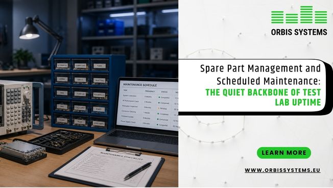
Spare Part Management and Scheduled Maintenance: The Quiet Backbone of Test Lab Uptime

Table of Contents

  1. The Real Cost of Unplanned Downtime
  2. Preventive Maintenance Planning and RF Equipment Lifecycle
  3. Spare Part Management for Reliable Testing Operations
  4. Building a Maintenance Scheduling Strategy for Labs
  5. Lifecycle Support and Long-Term Performance
  6. Conclusion
  7. Frequently Asked Questions

Spare Part Management and Scheduled Maintenance: The Quiet Backbone of Test Lab Uptime

Key Takeaways

  • Uptime is a planning outcome, not a lucky streak. Test lab uptime depends far more on proactive scheduling and inspection habits than on reacting quickly once something breaks.
  • Preventive maintenance catches problems while they’re small. Routine inspections, calibration checks, and planned part replacement give teams a chance to fix minor wear before it turns into a test-interrupting failure.
  • Spare part management removes the biggest bottleneck in repairs. Having critical components tracked and in stock means repairs can start immediately instead of waiting on procurement timelines.
  • Scheduling has to reflect real usage, not just a calendar. Equipment age, operating hours, environment, and maintenance history all shape a schedule that actually holds up under daily conditions.
  • Consistent maintenance extends the RF equipment lifecycle. Regular servicing reduces unnecessary wear and helps systems hold their calibration accuracy over a longer working life.
  • Lifecycle thinking beats treating maintenance as isolated events. Planning upgrades, repairs, and inventory together, rather than one at a time, gives labs a clearer long-term picture and fewer last-minute scrambles.


Ask most lab managers what keeps testing on schedule, and equipment quality comes up first. Skilled staff usually follows close behind. Maintenance rarely gets mentioned in the same breath, yet it shapes test lab uptime just as much as either of those factors. RF and automated test systems wear down through ordinary use. Cables loosen. Connectors degrade. Components age even when nothing appears wrong on the surface. 

Because of this, preventive maintenance planning, spare part management, and maintenance scheduling for labs tend to matter more than they get credit for. Labs that take these seriously typically deal with fewer surprises, get more usable years out of their equipment, and keep test schedules closer to plan.

The Real Cost of Unplanned Downtime

A test lab running on a tight schedule can absorb small setbacks. What it struggles with is the unplanned kind. One unexpected outage can delay product validation by days. It can push manufacturing decisions back further than anyone budgeted for. Research teams waiting on results end up waiting longer.

The disruption doesn’t end once the repair is finished, either. Engineers stop mid-test. Schedules get rearranged on short notice. Someone still has to figure out what actually caused the failure before work can pick back up, and that process alone can eat up hours or days depending on the system involved.

These costs build slowly, which is part of the problem. A lab dealing with occasional unplanned interruptions might not notice the pattern until a deadline slips. That’s really why more labs have started moving away from reactive repairs. Structured maintenance programs catch problems while they’re still minor. Finding an issue during a scheduled check costs far less, in time and disruption, than finding it in the middle of a test run.

Preventive Maintenance Planning and RF Equipment Lifecycle

RF test systems wear down for a few predictable reasons: constant operation, environmental exposure, and the simple aging of internal components. None of this happens overnight. Small changes accumulate, and if nobody’s watching, they eventually start affecting calibration accuracy and, in turn, the reliability of the results a lab depends on.

Preventive maintenance planning works by servicing equipment on a set schedule instead of waiting for a breakdown to force the issue. A maintenance program built around this idea usually touches on a handful of recurring tasks. Routine inspections come first, followed by calibration verification and cleaning of sensitive components. Firmware or software updates get applied where they’re needed. Parts known to wear out get replaced before they fail rather than after. Functional checks close out the process, confirming the system still performs the way it’s supposed to.

None of these steps is especially complicated by itself. The value comes from doing them on a consistent basis, month after month, rather than treating maintenance as something to get to eventually. That consistency is what actually preserves the RF equipment lifecycle, and it’s what keeps measurements repeatable, which matters more in production testing than almost anywhere else, since small inaccuracies there tend to carry real consequences downstream.

Talk to Orbis Systems About a Preventive Maintenance Plan

Spare Part Management for Reliable Testing Operations

A maintenance program can be well designed and still stall out if nobody has the right part on hand when it’s needed. This is where spare part management earns its place. Instead of waiting on procurement after something fails, labs that plan their inventory in advance can start repairs the same day.

A workable approach to spare part management starts with figuring out which components matter most to daily operations. From there, it’s mostly about visibility: keeping stock levels tracked for high-priority parts, noting when each one was last replaced, and adjusting inventory as equipment ages or usage patterns shift. Stock gets reviewed periodically alongside the broader maintenance schedule, not as an afterthought but as part of the same planning conversation.

Paired with scheduled maintenance services, this kind of planning stops being reactive and starts functioning as real risk management. Teams can swap out aging components during a planned service window rather than scrambling once something has already failed. The payoff is less downtime overall, and a testing environment that stays dependable instead of lurching from one repair to the next.

Effective spare parts management:

  • Reduces equipment downtime
  • Improves maintenance efficiency
  • Prevents production losses
  • Optimizes inventory costs
  • Ensures critical spares are available when needed


Building a Maintenance Scheduling Strategy for Labs

Putting dates on a calendar is only the surface layer of maintenance scheduling. A useful maintenance scheduling for labs strategy also has to account for how each system actually gets used day to day, what conditions it operates under, and how central it is to ongoing testing work.

Several factors shape this kind of planning. Equipment age is one. Operating hours matter too, along with the surrounding environment and whatever past maintenance records happen to show. Manufacturer guidance plays a role as well, though it’s rarely the only input. Labs that build their schedules around this combination of factors tend to see fewer unexpected failures, steadier equipment availability, and workloads that maintenance teams can actually plan around instead of reacting to.

There’s a longer-term payoff too. Regular test equipment maintenance builds a documented history for each system over time. That history makes future planning easier, and it gives teams a clearer sense of when a system is approaching the point where replacement makes more sense than another repair.

Lifecycle Support and Long-Term Performance

Commissioning new equipment feels like the finish line, but it’s really just the starting point. From there, every system moves through a much longer stretch that includes routine checks, occasional repairs, scheduled servicing, and eventual part replacement. Labs that treat maintenance as part of this whole stretch, rather than a string of separate events, tend to end up with better outcomes.

That’s really the value of lifecycle-focused planning. Instead of responding to each issue as it comes up, teams that think in terms of the full equipment life cycle can plan upgrades ahead of time, budget for replacements before they’re urgent, and manage inventory with a longer view in mind.

Orbis Systems supports this kind of thinking through spare part management, repair and maintenance services, and periodic scheduled maintenance, aimed at helping customers keep their testing environments dependable for as long as the equipment stays in service.

[Request a Lifecycle Support Consultation from Orbis Systems →]

Conclusion

Reliable testing doesn’t happen on its own. It gets built, gradually, through steady maintenance habits, spare part inventories that are actually organized, and schedules that reflect how equipment gets used rather than how a calendar template says it should. These practices rarely draw attention until something goes wrong. Labs that invest in them consistently tend to avoid that moment altogether.

As test environments keep growing more complex, treating maintenance as an ongoing lifecycle commitment rather than a response to breakdowns makes a real difference. Preventive maintenance planning, paired with solid spare part management and regular test equipment maintenance, supports stronger test lab uptime and a longer RF equipment lifecycle over time.

Orbis Systems offers lifecycle support built around periodic scheduled maintenance, repair and maintenance, and spare part management, helping labs maintain dependable performance across the full working life of their RF and automated test systems.

Frequently Asked Questions

1. Why is preventive maintenance important for test lab uptime?

Preventive maintenance helps catch small equipment issues before they grow into failures that interrupt testing. Routine inspections, calibration checks, and planned part replacement all support measurement accuracy and steadier system availability, and together these habits contribute directly to stronger test lab uptime.

2. What is spare part management in a testing laboratory?

Spare part management means identifying, storing, and tracking the components most likely to need replacement during repairs or routine maintenance. Having those parts ready ahead of time shortens repair delays considerably and helps testing systems get back online faster after an issue comes up.

3. How does maintenance scheduling improve laboratory operations?

A structured maintenance scheduling approach for labs lets servicing happen at planned intervals rather than only after equipment breaks down. This cuts down on surprise disruptions and gives maintenance teams a workload they can actually plan around instead of one they’re constantly reacting to.

Benefits:

  • Increased equipment reliability.
  • Increased Productivity
  • Better Spare Parts Planning
  • Reduced unplanned downtime
  • Extended equipment life
  • Improved safety
  • Lower repair costs
  • Higher Customer Satisfaction

4. How does regular maintenance extend the RF equipment lifecycle?

Routine inspections, calibration, cleaning, and timely part replacement all reduce unnecessary wear on RF systems over time. This kind of consistency helps preserve equipment performance and supports a longer, more reliable RF equipment lifecycle overall.

5. What services support long-term maintenance of RF test systems?

Long-term maintenance support usually includes scheduled maintenance services, test equipment maintenance, repair work, calibration support, and spare part management. Together, these services help labs maintain equipment reliability and reduce downtime across the full operational life of their systems.

Categories
Blogs

Programmable Attenuators and Phase Shift Matrix Modules: Precision Tools for Modern RF Labs

Table of Contents

  1. Why Precision Matters in RF Testing
  2. Understanding Programmable Attenuators
  3. What Is a Phase Shift Matrix Module?
  4. How the Two Work Together
  5. Where These Tools Are Used
  6. Choosing the Right Signal Control Solution
  7. Conclusion
  8. FAQs

Programmable Attenuators and Phase Shift Matrix Modules: Precision Tools for Modern RF Labs

Modern RF testing depends on tight control over signal strength and phase. Engineers validating wireless devices, checking antenna performance, or testing communication systems need tools that hold up across many test conditions, not just one. That reliability is the job of RF signal attenuation control, programmable attenuators, and phase shift matrix modules. Used together, these tools let RF laboratories automate testing, tighten measurement accuracy, and keep pace with increasingly complex wireless systems.

Key Takeaways

  • RF signal attenuation control helps keep power levels steady from the start of a test to the end, so results stay consistent even when conditions change.
  • Programmable attenuators let engineers adjust signal strength through software instead of swapping hardware by hand, which makes the process faster and easier to repeat.
  • A phase shift matrix module gives engineers a way to control phase accurately across several RF paths at once, which matters more as antenna and beamforming systems get more complex.
  • When attenuation and phase are managed together, RF signal conditioning becomes more reliable across the entire testing workflow, not just in isolated steps.
  • Precision RF calibration tools support long-term consistency, helping labs get dependable results across both wireless validation work and production testing.
  • Automated signal control cuts down on manual work, which reduces the chance of error and speeds up overall testing time.
  • Modular, scalable solutions give laboratories the flexibility to grow their setup as wireless standards and testing needs continue to change.

Why Precision Matters in RF Testing

Wireless technology keeps changing. Antenna systems have grown more advanced, operating frequencies have climbed, and performance expectations have gone up along with them. RF laboratories now need to recreate a wide range of signal conditions while keeping measurement accuracy steady from one test run to the next.

Small shifts in signal power or phase can throw off results in ways that are hard to trace later. This is why engineers lean on precision RF calibration tools to manage signal behavior at every stage of testing. Careful calibration also cuts down on measurement uncertainty, which in turn builds more confidence in the final results.

Good RF signal attenuation control lets engineers adjust signal levels without adding distortion they didn’t ask for. In a similar way, phase control in RF testing keeps signal behavior synchronized across multiple RF paths. That synchronization matters most in setups involving multiple antennas or beamforming, where timing between paths can make or break a test.

When attenuation and phase management are handled well together, RF laboratories end up with testing environments that hold steady across research projects, product validation, and manufacturing runs alike.

Understanding Programmable Attenuators

A programmable attenuator is an electronically controlled device that reduces RF signal power by a set amount. Fixed attenuators can’t be adjusted once installed, but programmable models let engineers change attenuation levels remotely, through software or as part of an automated test system.

That flexibility is what makes an RF programmable attenuator so useful in labs where test scenarios shift often, and signal levels need to change to match. Rather than swapping hardware by hand every time conditions change, engineers can set attenuation values through software, which speeds things up and removes a common source of error.

Some of the advantages worth noting:

  • Precise, repeatable adjustment of RF signal power across test cycles
  • Faster automated testing workflows with less manual setup
  • Remote software control that fits into larger integrated test systems
  • Consistent signal conditioning across a range of devices under test

A variable attenuator RF lab setup usually leans on programmable attenuation for exactly this reason. Multiple products, frequencies, and test conditions often need to run through the same shared infrastructure, and programmable control makes that possible without constant rewiring.

See how Orbis Systems’ programmable attenuator models fit into your test setup. Request a Free Consultation

What Is a Phase Shift Matrix Module?

Where programmable attenuators manage amplitude, a phase shift matrix module manages the phase relationship between RF signals.

Phase control has become more important as wireless systems move toward multiple antennas,controlling phase adjustment across multiple signal paths,By precisely altering the phase of RF signals, it enables beam steering, channel emulation, signal synchronization, and advanced testing applications.Engineers often need to introduce specific, controlled phase differences to see how a device responds under different signal conditions.

A phase shift matrix module makes those adjustments possible with a level of precision that manual methods can’t match, and it does so in a way that fits into automated test environments. Instead of adjusting individual signal paths by hand, engineers can set phase values through software and move on to the next test faster.

This kind of module typically supports:

  • Accurate phase adjustment across multiple RF channels at once
  • Automated multi-channel testing with less manual intervention
  • Better repeatability during antenna validation work
  • Signal synchronization that holds steady across test runs

As wireless technology advances, dependable phase control in RF testing has turned into a baseline requirement rather than an extra, particularly for teams evaluating communication performance and antenna behavior in detail.

How the Two Work Together

Few RF laboratories rely on just one signal control device. More often, programmable attenuators and phase shift matrix modules sit side by side in a larger automated test environment, each handling a different part of the job.

Programmable attenuators manage signal strength. Phase shift matrix modules manage timing and phase relationships. Put together, they give engineers the range to reproduce a wide variety of real-world operating conditions inside a controlled lab setting.

During antenna or wireless device validation, for instance, an engineer might need to lower signal power while introducing a specific phase difference across several RF paths at the same time. Doing both through software, rather than manual configuration, tends to produce more consistent results across repeated test runs.

This pairing also supports steady RF signal conditioning, giving engineers the means to fine-tune a test environment as validation requirements shift over the course of a project.

When these two technologies are folded into a shared automated workflow, laboratories generally see better repeatability, shorter setup times, and smoother handling of multiple concurrent projects.

Where These Tools Are Used

Programmable attenuation and phase control show up across a wide range of RF testing work, wherever precision and repeatability matter most.

Typical applications include:

  • Automated RF Test Systems
  • Wireless device validation
  • Antenna testing
  • Over-the-Air (OTA) testing
  • MIMO testing
  • Phased Array and Beamforming evaluation
  • Research and development labs
  • Manufacturing and production testing
  • RF calibration and validation environments

Across all of these, engineers depend on RF signal conditioning to keep test conditions stable while still adapting to each device’s specific requirements. As test complexity grows, both high-precision attenuator hardware and accurate phase management play a bigger role in producing results that hold up under scrutiny.

Choosing the Right Signal Control Solution

The right RF signal control setup depends on what a laboratory is trying to accomplish, how much automation it needs, and how complex its testing environment already is.

A few factors worth weighing before making a decision:

  • Required attenuation range and resolution
  • Accuracy and repeatability across test cycles
  • Number of RF channels involved
  • Software programmability and ease of integration
  • Compatibility with existing RF infrastructure
  • Room to scale as testing needs grow

A high-precision attenuator should hold its performance steady across repeated test cycles without drifting. A phase shift matrix module, in turn, should offer phase adjustments accurate enough to integrate cleanly into an automated workflow.

Organizations developing advanced RF test systems, including Orbis Systems, build programmable signal control components with these needs in mind. Their published solutions show how programmable attenuators and phase management technology can support flexible RF testing architectures without giving up measurement consistency.

Explore Orbis Systems’ full range of test and switching solutions. [View Solutions]

Conclusion

RF laboratories need more precision than ever as wireless systems keep getting more advanced. Programmable attenuators and a phase shift matrix module help meet that need by giving engineers control over both signal strength and phase, without relying on manual setup.

Together, these tools support RF signal attenuation control, dependable phase control in RF testing, and steady RF signal conditioning across a lab’s daily work. The result is less manual adjustment, faster setup, and results engineers can trust from one test to the next.

For labs working on wireless validation or production testing, reliable precision RF calibration tools remain a practical investment. Companies such as Orbis Systems continue to build modular solutions around this need, helping labs bring programmable signal control into automated test environments without losing accuracy.

Frequently Asked Questions 

What is an RF programmable attenuator used for?

An RF programmable attenuator is used to electronically adjust RF signal power levels electronically during testing. It allows engineers to make precise attenuation adjustments through software, which makes automated RF testing faster and more consistent than manual adjustment would allow.

Why is phase control important in RF testing?

Phase control in RF testing keeps signals aligned to the phase relationships a test requires. This matters most in antenna testing, beamforming evaluation, and MIMO systems, where multiple channels need to stay synchronized for results to mean anything.

How do programmable attenuators improve RF signal conditioning?

Programmable attenuators support RF signal conditioning by adjusting signal strength accurately without requiring engineers to swap hardware by hand. That helps labs maintain consistent test conditions across a wide range of validation scenarios.

What is the role of a phase shift matrix module?

A phase shift matrix module introduces controlled phase changes across RF channels. This lets engineers simulate different operating conditions and evaluate how a wireless system performs with a level of accuracy manual methods can’t reach.

How do programmable attenuators and phase shift matrix modules work together?

Programmable attenuators manage RF signal power, and phase shift matrix modules manage signal phase. Together, they give RF laboratories the combined control needed for better automation, repeatability, and measurement accuracy in modern test environments.

Categories
Blogs

Mesh Test System Explained: Validating Multi-Node Wireless Performance

Table of Contents

  1. What Is a Mesh Test System
  2. Why Multi-Node Wireless Testing Is Important
  3. How Mesh Router Validation Works
  4. Measuring Mesh Network Throughput
  5. Evaluating Whole-Home Mesh Performance With Multi-AP Testing
  6. The Value of Automation in Mesh Testing
  7. Building Confidence in Mesh Product Performance
  8. Frequently Asked Questions

Mesh Test System Explained Validating Multi-Node Wireless Performance

Most homes and offices no longer operate on a single router. They rely on a group of connected devices that need to behave as one network. This shift is the core reason mesh test systems have become an important part of modern wireless validation, allowing engineers to evaluate how connected devices behave together rather than judging each device on its own.

The scope covers multi-node wireless testing, mesh router validation, mesh network throughput, multi-AP testing, and whole-home mesh performance. Mesh setups are now common in residential, business, and IoT environments, and that shift is exactly why structured testing matters before a product enters the market.

Key Takeaways

  • Mesh networks are best validated at the system level, not device by device.
  • Multi-node wireless testing shows how mesh devices actually communicate with one another.
  • Mesh router validation confirms stable operation across every node in the network.
  • Mesh network throughput is a direct measure of how efficiently and consistently the network performs.
  • Multi-AP testing helps evaluate roaming, coverage, and how well the network scales.
  • Whole-home mesh performance testing supports a consistent user experience across larger spaces.

What Is a Mesh Test System

A mesh test system evaluates devices working together as a coordinated mesh, rather than as isolated routers. The focus shifts from single-device performance to how nodes interact, how client devices roam between them, and how the network holds together as conditions change.

This is where multi-node wireless testing becomes central. Rather than measuring a single router in isolation, it captures how the entire network responds under real operating conditions. Conducting this inside a controlled RF environment removes outside interference, and that level of control is what makes results repeatable from one test cycle to the next.

This approach is also reflected in companies such as Orbis Systems, where a structured mesh connectivity test setup is built specifically for repeatable, lab-based evaluation between mesh nodes.

Why Multi-Node Wireless Testing Is Important

Mesh networks introduce a specific challenge: a single weak node can affect the performance of the entire system. An access point with a communication issue can reduce throughput, add latency, or disrupt connections across every other node in the network. This is why multi-node wireless testing cannot be limited to evaluating individual devices. It also needs to trace how data moves between nodes and where that movement begins to break down.

Engineers commonly evaluate:

  • Communication quality between mesh nodes
  • Roaming performance as client devices move through the coverage area
  • Stability of the backhaul connection
  • Signal behavior under changing conditions
  • How the network responds as new nodes are added
  • Identifying these issues during testing, rather than after installation, helps manufacturers avoid costly problems once a product is already in the field.

How Mesh Router Validation Works

Validation is less about whether a router powers on and more about whether it performs its role alongside every other node in the mesh. Mesh router validation examines both how each router performs on its own and how the group performs together across a range of test conditions.

In practice, this involves testing the wireless links between routers, monitoring how client devices transition from node to node, timing how quickly the network recovers after a disruption, and confirming that communication stays steady across the full setup.

An automated mesh test system helps reduce much of the manual effort involved in this process. It also makes it easier to compare results from one product version against another as development continues.

Wireless technology continues to evolve, and mesh router validation remains one of the more consistent ways to catch design issues that would otherwise surface after deployment.


Measuring Mesh Network Throughput

One number tends to indicate how a mesh network is actually performing: mesh network throughput. It measures how efficiently data moves through the system while multiple nodes handle traffic simultaneously.

Testing this is not as simple as measuring a single router. Engineers also need to account for backhaul traffic, the physical placement of each node, how client devices are distributed, and how much data is moving through the network at any given time.

In practical terms, this typically involves measuring end-to-end throughput across every node, throughput while a client is actively roaming, how traffic distributes between access points, performance once the network is under heavier load, and whether results remain steady across repeated runs.

Reliable throughput numbers indicate how well a network keeps up as the mesh grows more complex. Running these tests inside a controlled RF environment keeps measurements consistent, which is what makes it possible to compare results between one test cycle and the next.

Evaluating Whole-Home Mesh Performance With Multi-AP Testing

Consistent coverage across an entire home is one of the primary expectations for a modern mesh product. Coverage needs to hold up throughout the space, not only near the primary router.

Rather than testing routers individually, engineers use multi-AP testing to evaluate how multiple access points work together to maintain steady coverage across an entire area.

This kind of testing typically covers:

  • How smoothly clients roam between access points
  • Whether coverage remains even across different rooms or zones
  • How load balances between nodes
  • How quickly the network recovers after a dropped connection
  • Whether performance holds steady as more nodes are added

The result is a realistic picture of whole-home mesh performance, one that indicates how a product is likely to behave once installed in a real environment. Because the testing environment is controlled, teams can recreate the same conditions later, which becomes important when validating a firmware update or a new hardware revision.

For companies building residential mesh products, repeated testing of whole-home mesh performance is one of the more reliable methods for maintaining a consistent end-user experience. Some teams also pair this with RVR Wi-Fi testing to gain a broader view of performance across more complex setups.

The Value of Automation in Mesh Testing

Manual testing can work well for basic validation, but mesh products are complex by design. Automated testing addresses this by running the same procedures repeatedly without requiring manual intervention, which also removes much of the inconsistency that manual work can introduce.

Automation supports faster execution of complex test scenarios, keeps measurements steady from run to run, and makes it easier to compare results across product versions. It also supports regression testing and allows teams to take on larger validation projects without increasing time or headcount.

Multi-node wireless testing and mesh router validation both involve coordinating multiple devices and metrics at the same time, which is why automation tends to be essential rather than optional. This engineering-led approach is reflected in companies such as Orbis Systems, where automation is built into the structured wireless testing platforms developed for mesh validation.

Building Confidence in Mesh Product Performance

Mesh networks are becoming increasingly common, which means validating performance across multiple nodes is no longer optional. A mesh test system gives engineers a structured way to carry out multi-node wireless testing, complete mesh router validation, measure mesh network throughput, perform multi-AP testing, and evaluate whole-home mesh performance, all under conditions that can be controlled and repeated.

Combining this structured approach with automation gives manufacturers a level of confidence in their products that manual testing alone cannot easily match. This is aligned with the integrated RF testing focus seen in companies such as Orbis Systems, where wireless validation platforms are developed to support consistent, repeatable measurement environments for modern mesh products.

Frequently Asked Questions

1. What is a mesh test system?

A mesh test system is a testing platform built to evaluate how well a wireless mesh network performs by measuring how multiple connected nodes communicate under controlled lab conditions.

2. Why is multi-node wireless testing important?

Multi-node wireless testing shows engineers how several devices operate together, which is what supports stable communication, reliable roaming, and consistent performance before a product enters the field.

3. What does mesh router validation measure?

Mesh router validation examines how routers and access points communicate with each other, how they handle client roaming, how stable their wireless links remain, and how they perform under different network conditions.

4. Why is mesh network throughput an important metric?

Mesh network throughput indicates how efficiently data moves through a mesh network while multiple nodes exchange traffic simultaneously, which makes it one of the clearer signals of how the network is actually performing.

5. How does multi-AP testing improve whole-home mesh performance?

Multi-AP testing examines coverage continuity, roaming behavior, traffic distribution, and how well nodes coordinate with one another, all of which help engineers refine whole-home mesh performance before a product reaches deployment.

Categories
Blogs

RF Tunnel Shielded Chambers: A Different Approach to Interference-Free Testing

Table of Contents

  1. Why Interference-Free RF Testing Matters
  2. Understanding RF Tunnel Shielded Chambers
  3. How Tunnel-Style RF Shielding Supports Reliable RF Testing
  4. Applications of RF Tunnel Shielded Chambers
  5. Key Factors When Selecting an RF Tunnel Shielded Chamber
  6. Key Takeaways
  7. Conclusion
  8. Frequently Asked Questions

RF Tunnel

Wireless technology moves fast, and testing has to keep pace with it. An RF Tunnel Shielded Chamber gives engineers a way to test devices in a controlled RF environment without slowing down the flow of equipment through a lab or production line. The chamber blocks outside electromagnetic signals from entering the test area, so measurements stay accurate and repeatable from one test run to the next. Teams working on 5G, IoT, Wi-Fi, and automotive wireless systems often need this kind of setup, since it combines strong shielding with a layout that fits real-world workflows rather than forcing devices to sit in one fixed spot.

Key Takeaways

  • Tunnel-style RF shielding creates a controlled pathway that supports reliable wireless testing while reducing external electromagnetic interference.
  • An RF isolation environment improves measurement repeatability for OTA, antenna, and wireless device validation.
  • A walk-through shielded chamber can support production-oriented workflows where products move through multiple testing stages.
  • Proper chamber design, absorber configuration, and shielding effectiveness contribute to accurate and repeatable RF measurements.
  • Orbis Systems offers RF Tunnel Shielded Chambers as part of its RF chamber solutions for controlled wireless testing environments.

Why Interference-Free RF Testing Matters

Radio frequency bands are busier today than they used to be. A nearby Wi-Fi network, a piece of industrial equipment, or even another lab bench running its own tests can quietly distort a measurement if the testing space isn’t properly shielded.

This is where a controlled RF isolation environment earns its value. It limits what reaches the device under test, which means engineers can trust that what they’re measuring reflects the device itself and not some outside signal bleeding into the results. This becomes especially important during antenna work, OTA validation, and throughput testing, where a small amount of stray interference can change how a result reads.

New standards keep entering the picture, too. Wi-Fi 7 and private 5G deployments are two recent examples. Each one adds pressure to keep test conditions steady across long development cycles, not just for a single test session.

Understanding RF Tunnel Shielded Chambers

At its core, an RF-shielded chamber keeps testing activity separate from the outside electromagnetic environment. A tunnel-style version stretches that idea into a longer shielded path, one that a product or piece of equipment can travel through while staying inside a shielded zone the entire time.

That’s a meaningful difference from a chamber that’s fully closed off. A walk-through shielded chamber suits teams whose devices need to keep moving, whether between test stations or through stages of a manufacturing line. The tunnel shape keeps the shielding intact while leaving room for larger devices or a direct connection to production equipment.

Many of these chambers also include RF-absorbing material inside, which cuts down on internal reflections that would otherwise interfere with a clean reading. Shielding keeps outside noise out; absorption keeps the inside quiet too, and together they create the stable conditions RF measurement depends on.

Orbis Systems builds its RF Tunnel Shielded Chamber around this idea. It’s a fully shielded, configurable enclosure meant for dependable over-the-air testing, and it sits within a broader lineup of chamber solutions built for wireless testing at different scales. The chamber is built on Orbis’ existing OTA and shielding platforms, with antenna positioning and DUT interfaces already worked into the design so automated validation doesn’t require a separate setup. It covers both Sub-6 GHz (FR1) and mmWave (FR2) ranges, which makes it a fit for full 5G device and base station testing

Curious whether a tunnel-style chamber would work for your test floor? 

[Request a Consultation with Orbis Systems ]

How Tunnel-Style RF Shielding Supports Reliable RF Testing

The point of tunnel-style RF shielding is to hold RF isolation steady through the whole testing process, not just while a device sits still. Rather than depending on one sealed room, the tunnel design creates a shielded path so a device stays protected from outside interference, whether it’s being evaluated or simply moving through.

A few things make this work in practice. The shielded construction stops outside RF signals from getting in. The absorbing material inside cuts down on reflections that could otherwise throw off a reading. The layout itself can be adjusted to fit different device sizes or different testing workflows, so one chamber design doesn’t have to be replaced every time requirements shift. And where automated positioning or production systems are already in place, the chamber can work alongside them to keep testing consistent over time.

Orbis Systems adds another layer here through its own antenna positioners and DUT controllers, which connect through standard REST API support. That means antenna alignment, beamforming, MIMO, and throughput testing can run with far less manual setup than they otherwise would. The chamber also comes in a few different formats, including tunnel-style shielded rooms, container-based OTA chambers, and smaller shielded boxes, so a lab can start small and scale up toward a full production deployment without switching platforms.

Put together, this is what engineers usually mean when they describe a chamber as EMI-free: one that keeps producing results they can trust, test after test. For OTA work, antenna evaluation, or general wireless validation, steady shielding conditions cut down on variability and give engineers more confidence in what they’re seeing.

Applications of RF Tunnel Shielded Chambers

An RF isolation chamber built this way tends to show up across a wide range of testing work. OTA testing for wireless devices is a common use. Antenna performance evaluation is another. Beyond that, these chambers support wireless module validation, production-line RF testing, IoT device verification, automotive wireless system testing, and validation of industrial wireless equipment.

A walk-through shielded chamber tends to be the more practical choice in settings where products move between several testing stations, since it keeps the RF environment controlled without forcing a stop-and-start process. As wireless products keep adding complexity, holding an interference-free test environment through the full validation process makes a real difference in how consistent the results end up being.

Orbis Systems positions its RF Tunnel Shielded Chamber as part of a larger set of chamber solutions, covering everything from smartphone OTA validation to automotive and defense testing to on-site verification using container-based chambers that can be deployed where needed.

Key Factors When Selecting an RF Tunnel Shielded Chamber

Picking the right chamber usually comes down to a mix of technical requirements and day-to-day workflow needs. Engineers tend to look at shielding performance first, then work through how well a given design fits into their existing process.

Shielding effectiveness across the frequency range being tested is typically the starting point, alongside the chamber’s dimensions relative to the device under test. From there, the internal absorber setup affects how well reflections are managed, and whether the chamber can connect with automation or production systems often shapes how well it fits into a larger test line. How easily equipment can move in and out, and how well the chamber connects with existing RF measurement systems, round out the rest of the decision.

The specific application usually points toward the right choice, whether that’s a standard chamber, an RF-shielded test enclosure, or a tunnel-style setup. Teams handling large devices or running continuous production tend to lean toward the tunnel design, while smaller validation projects are often served well enough by a more compact shielded setup.

Not sure which configuration fits your production line? 

[Talk to an Orbis Systems Engineer]

Conclusion

Wireless technology isn’t slowing down, and neither are the demands placed on RF testing. An RF Tunnel Shielded Chamber offers a practical alternative to a fully enclosed room by pairing solid shielding with a layout that works with real production and lab workflows instead of against them. Through tunnel-style RF shielding, engineers get an RF isolation environment that supports interference-free testing while keeping results consistent across a wide range of wireless applications.

Anyone reviewing their current RF testing setup will likely find that understanding the differences between chamber types makes the decision easier. Orbis Systems offers configurable RF Tunnel Shielded Chambers as part of a wider chamber portfolio, all built around the same idea of controlled, repeatable wireless testing.

Frequently Asked Questions

What is an RF Tunnel Shielded Chamber?

An RF Tunnel Shielded Chamber is a shielded testing environment designed to keep wireless testing isolated from outside electromagnetic interference while still letting devices or equipment move through a tunnel-style layout. It supports controlled RF measurement across a wide range of wireless applications.

How does a tunnel-style RF shielding design differ from a conventional RF shielded chamber?

A conventional RF shielded chamber is usually a fully enclosed space. A tunnel-style design instead offers an extended shielded path, one that works better with continuous workflows, larger equipment, or production-line testing, all while keeping the RF isolation intact.

What types of testing can be performed inside an RF isolation chamber?

An RF isolation chamber supports OTA testing, antenna evaluation, wireless device validation, RF performance measurement, throughput testing, and other verification work that depends on controlled electromagnetic conditions.

Why is interference-free RF testing important?

Interference-free RF testing keeps outside electromagnetic signals from skewing measurement results. That leads to more consistent testing, more repeatable measurements, and a more reliable read on how a wireless device actually performs.

Where can I learn more about RF Tunnel Shielded Chambers?

You can learn more about RF Tunnel Shielded Chambers and other RF testing solutions by visiting Orbis Systems’ RF Tunnel Shielded Chamber page: https://www.orbissystems.eu/solutions/rf-tunnel-shielded-chamber/

Categories
Blogs

Wi-Fi 7 and Wi-Fi 8: What RF Test Labs Need to Know Before the Next Wave

Table of Contents

  • Why Wi-Fi Testing Is Changing
  • Key Testing Areas for Wi-Fi 7
  • Looking Ahead to Wi-Fi 8
  • Why Automation Matters in RF Testing
  • Building a Future-Ready Test Lab
  • Conclusion
  • Frequently Asked Questions

Wireless technology is moving forward quickly, and RF test labs are expected to keep pace with every new development. Today, Wi-Fi 7 testing is becoming an important part of wireless product validation because devices now support higher data rates, wider channels, and more advanced communication features.

At the same time, many engineering teams are already looking ahead to the requirements of a Wi-Fi 8 RF lab. Although Wi-Fi 8 is still developing, planning for future testing needs can help laboratories stay ready for upcoming wireless standards. 

This article explains the key changes that RF test labs should understand and how they can prepare for the next stage of wireless testing, including the growing importance of RVR Wi-Fi testing in supporting repeatable wireless performance evaluation.

Key Takeaways

  • Wi-Fi 7 brings wider channels, Multi-Link Operation, and higher throughput, which increase testing requirements.
  • Early planning helps laboratories prepare for future Wi-Fi technologies.
  • Automation supports accurate and repeatable RF measurements.
  • Wireless validation now includes interoperability, throughput, and mesh network performance.
  • Flexible RF test environments make it easier to support future wireless standards.

Why Wi-Fi Testing Is Changing

Every new wireless generation introduces new features that improve performance. However, these improvements also make product validation more demanding. Modern wireless devices are expected to deliver fast connections, stable performance, and reliable communication across different environments. Because of this, RF testing now covers much more than basic connectivity.

Engineers need to evaluate antenna performance, signal quality, throughput, and device behaviour under different operating conditions. They also need testing environments that provide accurate and repeatable measurements every time. Therefore, Wi-Fi 7 testing has become a key step in product development for many wireless manufacturers.

In addition, many organizations are beginning to review how their current infrastructure can support the future needs of a Wi-Fi 8 RF lab. Planning early allows laboratories to make improvements gradually instead of making major changes later.

Key Testing Areas for Wi-Fi 7

Wi-Fi 7 (IEEE 802.11be) operates across three distinct frequency bands: 2.4 GHz, 5 GHz, and 6 GHz. This tri-band architecture enables backward compatibility with legacy Wi-Fi devices while introducing massive throughput upgrades via the newer, less congested 6 GHz spectrum

Wi-Fi 7 introduces several new capabilities that improve wireless performance. At the same time, these features increase the amount of testing required before products are ready for the market.

Multi-Link Operation Testing

One of the biggest changes is multi-link operation testing. Multi-Link Operation allows a device to send and receive data over more than one wireless link at the same time. As a result, devices can improve speed, reduce delays, and make better use of available wireless resources.

Multi-Link Operation (MLO): Wi-Fi 7 enables clients to aggregate channels across different bands (e.g., using a 320MHz channel in 6GHz while simultaneously linking to 5GHz). Testing MLO ensures both radios work seamlessly to prevent packet drops and lower latency.

However, this feature also means engineers need to confirm that the device performs consistently while managing multiple links together. Testing should be carried out in a controlled RF environment so that measurements remain accurate and repeatable throughout the validation process.

320MHz Channel Testing

Another important requirement is 320MHz channel testing. Wi-Fi 7 supports wider channels than earlier generations, allowing higher data rates where spectrum is available.

Testing wider channels requires careful control of the RF environment because small changes can affect measurement results. Therefore, laboratories need consistent test conditions throughout the validation process.

Important areas include:

  • Stable RF measurement conditions
  • Accurate antenna positioning
  • Repeatable test results
  • Reliable Wi-Fi throughput testing
  • Controlled interference levels

Important areas

In addition, engineers often perform Wi-Fi throughput testing under different operating conditions to understand how devices perform during continuous use rather than only measuring peak speeds.

Looking Ahead to Wi-Fi-8

Although Wi-Fi 8 specifications are still being developed, many engineers believe preparation should begin well before products reach the market. Building a Wi-Fi 8 RF lab is not only about supporting higher speeds. It is also about creating a flexible testing environment that can adapt as wireless technology continues to change.

For this reason, laboratories are reviewing their current testing processes, equipment, and automation capabilities. Early planning makes it easier to support future validation requirements without interrupting ongoing development work.

Many laboratories are also focusing on testing methods that improve repeatability, reduce manual work, and support consistent measurement quality across different wireless products.

Why Automation Matters in RF Testing

As testing becomes more detailed, automation plays a larger role in daily laboratory work. Manual testing is still valuable, but it can become time-consuming when engineers need to repeat the same measurements many times.

An automated positioning system helps move the device under test in a controlled and repeatable way. Because each measurement is performed from a known position, engineers can compare results more confidently throughout the testing process.

Automation also supports testing efficiency by reducing manual adjustments and helping laboratories complete larger validation programs while maintaining measurement consistency.

Furthermore, repeatable positioning becomes increasingly important as Wi-Fi 7 testing continues to include more advanced wireless features and larger test datasets.

Building a Future-Ready Test Lab

As wireless devices become more advanced, RF laboratories need testing environments that support both current and future technologies. A flexible test lab helps engineers adapt to new requirements without making major changes to the testing process.

An important part of wireless validation is wireless interoperability testing. Devices are expected to work reliably with different access points, client devices, and network configurations. Testing these combinations helps identify compatibility issues before products reach the market.

Mesh network testing is also becoming more important as mesh networks are widely used to improve wireless coverage. Engineers need to evaluate how devices perform while moving between connected access points to better understand real-world performance.

In addition, RVR Wi-Fi testing supports repeatable evaluation of wireless performance under controlled laboratory conditions. It helps engineers compare results across different test scenarios with greater consistency.

Modern RF laboratories also place greater focus on Wi-Fi throughput testing. Engineers need to evaluate not only peak data rates but also how devices perform during longer operating periods and under different traffic conditions.

As wireless technologies continue to evolve, testing requirements will continue to grow. Therefore, many laboratories are preparing their infrastructure to support future wireless standards. Orbis Systems highlights the value of controlled RF environments, accurate positioning, and repeatable measurements through its published RF and OTA testing solutions. 

Conclusion

Wireless technologies are becoming more capable with every new generation. As a result, RF validation is also becoming more detailed and more demanding. Features such as wider bandwidth, Multi-Link Operation, and higher throughput require laboratories to perform more comprehensive testing while maintaining accurate and repeatable measurements.

Today, Wi-Fi 7 testing is helping engineers validate products that support these advanced capabilities. At the same time, planning for a Wi-Fi 8 RF lab allows organizations to prepare for future wireless requirements without waiting for new standards to be fully introduced.

A flexible RF testing environment, supported by automation and consistent measurement processes, helps laboratories remain ready for future developments. As wireless technologies continue to progress, Orbis Systems continues to focus on RF testing environments that support accurate and repeatable wireless validation.

Frequently Asked Questions

What is Wi-Fi 7 testing?

Wi-Fi 7 testing is the process of evaluating the RF and wireless performance of devices that support the Wi-Fi 7 standard (IEEE 802.11be) . It includes testing areas such as throughput, channel bandwidth, antenna performance, and wireless communication under controlled laboratory conditions. The goal is to confirm that devices perform reliably before they are released for commercial use.

Why is Multi-Link Operation testing important?

Multi-link operation testing is important because Wi-Fi 7 devices can communicate over multiple wireless links at the same time. Engineers need to verify that these links work together correctly under different operating conditions. Proper testing helps confirm reliable performance, stable communication, and consistent measurement results.

What is involved in 320MHz channel testing?

320MHz channel testing focuses on evaluating device performance across the wider channels introduced with Wi-Fi 7. Engineers assess signal quality, throughput, RF behavior, and measurement consistency while working in a controlled testing environment. Accurate testing helps ensure reliable wireless performance across supported bandwidths.

Why is wireless interoperability testing necessary?

Wireless interoperability testing checks whether a device can communicate correctly with different access points, client devices, and network configurations. This process helps identify compatibility issues before products are deployed and supports reliable performance across different wireless environments.

How can RF laboratories prepare for Wi-Fi 8?

Although Wi-Fi 8 is still under development, laboratories can begin preparing by reviewing their testing infrastructure, improving automation, and building flexible RF environments that support future wireless technologies. Planning early also helps laboratories adapt more efficiently as new testing requirements become available. 


Categories
Blogs

How to Choose the Right Industrial Testing Equipment for Your Facility

Table of Contents

  1. Understand Your Testing Requirements
  2. Select the Right test and measurement equipment
  3. Why Reliable Test System Performance Matters
  4. The Value of Automation and System Integration
  5. Choosing Industrial Battery Testing Equipment
  6. Consider Future Scalability
  7. Invest in a Testing Environment That Supports Long-Term Performance
  8. Frequently Asked Questions

How to Choose the Right Industrial Testing Equipment for Your Facility

Choosing the right industrial testing equipment is harder than it looks. Most facilities assume it comes down to specs and price, but that usually leads to buying equipment that works fine on paper and causes headaches in practice. The testing equipment in your facility affects measurement accuracy, product quality, and day-to-day operational flow in ways that are easy to underestimate until something goes wrong.

These days, a growing number of facilities are moving away from standalone instruments and toward Industrial Testing Solutions that connect instruments, automation, and software into one working system. This guide breaks down what to actually consider when making that choice, addresses what essential equipment is for battery testing in industrial settings, and covers what reliable test system performance really requires.

Key Takeaways

  • Choose industrial testing equipment based on your facility’s real testing needs, not just specification comparisons.
  • Select test and Measurement Equipment that delivers accurate and consistent results across all testing stages.
  • Treat reliable test system performance as a core operational requirement, not a secondary consideration.
  • Look for Industrial Testing Solutions that genuinely support automation, scalability, and efficient workflows.
  • Plan long-term infrastructure around integrated test systems, automated test systems, and system integration testing from the start.
  • Verify that industrial battery testing equipment properly covers electrical, thermal, and performance validation for your specific application.

Understand Your Testing Requirements

Before looking at any equipment, stop and think about what your facility actually does. This sounds obvious, but a surprising number of purchasing decisions skip this step entirely and end up with mismatched setups.

Production volume, product type, facility conditions, and measurement precision requirements all point toward different kinds of equipment. A research lab needs flexibility above everything else. Setups change depending on the project, and rigid systems get in the way. A manufacturing floor needs the opposite. Consistency matters more than flexibility there. Processes have to run the same way every time, across every shift.

Getting clear on which of those situations describes your facility saves money and prevents a lot of frustration down the road. It also makes it much easier to align equipment decisions with what engineering and production teams actually need day to day.

Select the Right Test and Measurement Equipment

Industrial testing setups almost always involve multiple instruments, not one. The combination of test and measurement equipment that works depends on the application, and just as important as what each instrument does is how well they work together.

Equipment that typically appears in industrial testing includes:

  • power supplies and electronic loads
  • oscilloscopes and digital multimeters
  • signal generators and spectrum analyzers
  • data acquisition systems and switching systems
  • environmental test chambers and custom test fixtures

Pulling these together into integrated test systems tends to give better results than running them as separate units. Instruments that talk to each other reduce manual steps, keep data collection cleaner, and help testing stay consistent rather than varying between runs for no obvious reason.

Why Reliable Test System Performance Matters

Good instruments are necessary. They are not sufficient on their own. The full testing environment needs to produce repeatable results consistently, and that does not happen automatically just because the individual instruments are high quality.

Reliable test system performance comes from several things working together. System design, calibration schedules, controlled testing conditions, and clear procedures all play a part. When one of those breaks down, variability starts creeping into results in ways that can be genuinely difficult to diagnose.

There is also a practical cost argument here. Catching a product issue at the testing stage is far cheaper than catching it later. As production volume increases, that gap widens fast. Small inconsistencies that seem manageable at low volumes become expensive rework problems at scale. Building an environment that stays stable over time is one of the most practical things a facility can do for long-term efficiency. That stability is what separates useful Industrial Testing Solutions from those that just look good in a proposal.

The Value of Automation and System Integration

Production environments are always under pressure to go faster. That pressure is real, but speed without accuracy just moves the problem somewhere else. Automated test systems are useful precisely because they let facilities move faster without introducing the inconsistency that manual processes tend to bring in.

When a test sequence runs automatically, it runs identically every time. That removes a large source of variation. Results get logged automatically, too, which makes traceability much more manageable than relying on manual entry.

Adding system integration testing to the picture means instruments, software, and control systems stop operating as isolated pieces and start working as one environment. Maintenance becomes less complicated. Upgrades are less disruptive. When production needs change, which they always do eventually, adding to an integrated setup is usually far more practical than replacing separate systems one by one.

Choosing Industrial Battery Testing Equipment

Battery technology has moved fast across automotive, energy storage, telecom, and industrial electronics, and that pace is not slowing down. The demand for industrial battery testing equipment that can keep up with more complex products while still producing accurate results has grown considerably because of this.

The question of what essential equipment is for battery testing in industrial settings does not have a single fixed answer. It depends on battery chemistry, application, and validation requirements. That said, industrial battery testing generally needs to cover electrical performance, charge and discharge behavior, capacity, internal resistance, thermal response, and long-duration cycling performance. Covering all of that requires multiple instruments working in coordination.

Equipment that supports synchronized data collection and consistent measurement across these parameters gives manufacturers a solid validation foundation. It also keeps the setup adaptable as battery designs continue to evolve. A testing environment that can grow and adjust is genuinely more useful than one that has to be rebuilt every time a new chemistry or format comes into production.

Consider Future Scalability

Testing requirements change over time. New products arrive, volumes go up, regulations shift, and technology creates new demands that did not exist a few years ago. None of that is unusual. What matters is whether the testing environment can handle those changes without requiring a complete overhaul.

Modular designs and flexible software platforms make expansion possible without replacing everything. Scalable Industrial Testing Solutions allow facilities to add instruments, bring in more automation, or expand measurement channels within an existing framework. That keeps costs lower and keeps disruption to production minimal when changes are needed.

When evaluating Industrial Testing Equipment, it is worth asking directly whether the system can realistically support additional automation, more channels, and new validation requirements a few years out. That question is easy to overlook during initial selection and tends to matter a great deal later.

Invest in a Testing Environment That Supports Long-Term Performance

The right industrial testing equipment is not just about accurate readings today. It is about building an environment that holds up over time, scales with production, and stays reliable as requirements shift. clear testing goals, the right test and measurement equipment, and genuine planning for future needs are what make that possible, rather than just intended.

Orbis Systems has practical expertise in engineering and integrated test systems, and works with organizations to build testing environments that hold up under real industrial conditions. Investing in well-designed industrial testing solutions gives facilities a foundation that supports growth rather than creating new limitations every time demands change.

Frequently Asked Questions

What is Industrial Testing Equipment?

Industrial Testing Equipment covers the instruments and systems used to evaluate product performance, safety, functionality, and quality across research, development, validation, and manufacturing. Having the right testing equipment is a basic requirement that directly affects product quality and production consistency.

Why is reliable test system performance important?

Reliable test system performance keeps measurements accurate from one cycle to the next and stops small errors from turning into costly production problems. Without it, variability builds up and surfaces as rework, delays, or quality failures that are far more expensive to fix later.

What are essential equipment for battery testing in industrial settings?

Industrial battery testing generally requires power supplies, electronic loads, digital multimeters, data acquisition systems, battery cyclers, temperature monitoring tools, and control software. These instruments need to work together in a coordinated setup, especially as battery designs grow more complex.

How do automated test systems improve industrial testing?

Automated test systems remove manual steps from the testing process, reducing operator error and keeping results consistent across every cycle. Documentation is handled automatically through standardized reports, which keep records organized and easy to review.

How do integrated test systems benefit manufacturing facilities?

Integrated test systems bring instruments, software, automation, and communication interfaces into one environment, making testing more consistent and system management simpler. When requirements grow or change, expanding an integrated setup is far more manageable than connecting systems that were never designed to work together.

Categories
Blogs

RF Switch Matrix Architectures: Blocking vs. Non-Blocking: Which Do You Need?

Table of Contents

  1. Why RF Switch Matrix Architecture Matters
  2. Understanding Blocking RF Switch Matrix Architecture
  3. Understanding Non-Blocking RF Switch Matrix Architecture
  4. Blocking vs. Non-Blocking: A Comparison
  5. Choosing the Right Architecture for Your Application
  6. How Architecture Affects RF Measurement Accuracy
  7. Conclusion
  8. Frequently Asked Questions

RF Switch Matrix Architectures: Blocking vs. Non-Blocking:

If you are setting up a wireless test environment, one of the first things you need to figure out is which RF switch matrix architecture to go with. This single decision affects how signals move through your system, how clean your measurements come out, and whether the setup can handle more work down the road. It does not matter if you are building an RF switching system for a lab or putting together test automation systems for a production floor. Either way, understanding both options before you commit saves you from a lot of headaches later. This article goes through the key differences and what actually matters when making this call.

Key Takeaways

  • The RF switch matrix architecture you go with shapes routing flexibility, scalability, and automation performance directly.
  • Blocking architectures are a solid option for structured production workflows where signal paths stay consistent.
  • Non-blocking architectures are the better fit for research environments and multi-device testing, where flexibility is non-negotiable.
  • Choosing the right architecture leads to better RF measurement accuracy and more consistent test outcomes.
  • Thinking through future growth needs before you build helps test automation systems stay effective for the long haul.

Why RF Switch Matrix Architecture Matters

At its core, an RF switch matrix moves RF signals automatically between instruments, devices under test, antennas, and measurement tools. You do not have to touch a single cable every time a test setup changes because the software handles all the routing. This cuts down on time and keeps mistakes low.

That said, the architecture behind the system is what determines how well all of this actually works. Things like how flexible the routing is, how clean the signal stays, how repeatable your measurements are, and how much room the system has to grow all come down to this one choice. If you get it wrong early on, fixing it later takes real time and money.

Understanding Blocking RF Switch Matrix Architecture

A blocking RF switch matrix runs on a fixed group of signal paths. If one path is already being used, another path you want may have to wait until that first one clears. So some routing combinations simply cannot run at the same time.

Still, blocking architectures are used all the time and for good reason. They keep things simpler, cost less, and still perform well for most test environments. The reality is that most setups do not need every possible connection running at the same moment. A 6×6 RF switch or a 4×24 RF switch are common example where the layout is matched to the number of instruments and devices the system needs to handle.

Blocking architectures work well for:

  • Sequential RF testing, where one path runs at a time
  • Production lines that follow the same steps repeatedly
  • Applications where only a handful of simultaneous connections are needed
  • Systems where keeping costs and complexity low is important

As long as the design is done properly, a blocking architecture gives you reliable measurements and good support for automated testing.

Understanding Non-Blocking RF Switch Matrix Architectures

A non-blocking architecture does not have those same path restrictions. Any input can connect to any available output, and other signal paths can still run at the same time without any conflict. This opens up a lot more options for how you route signals across the system.

Non-blocking systems show up most often in labs where several devices or measurements need to be running at once. They take routing restrictions out of the equation and make it far easier to manage flexible test setups inside advanced test automation systems. They do require more switching hardware and more planning upfront, but the payoff is a system that can handle shifting test needs without running into walls.

These architectures are commonly used in:

  • Multi-device validation testing
  • Research and development labs
  • Large-scale automated RF measurement setups
  • Wireless testing environments where test configurations change often

Blocking vs. Non-Blocking: A Comparison

Feature Blocking Architecture Non-Blocking Architecture
Routing flexibility Limited by fixed paths Any input can connect to any output
Simultaneous connections Restricted in some cases Multiple independent paths supported
System complexity Lower Higher
Scalability Good for many production setups Better for growing test environments
RF measurement accuracy High when properly designed High with greater routing flexibility
Automation capability Works well for sequential testing Best for complex automated testing
Typical applications Production testing, fixed workflows R&D labs, advanced wireless testing


Choosing the Right Architecture for Your Application

There is no one-size-fits-all answer here. What works for one team may not work for another. Your workflow, your growth plans, and what you need from automation all play a role in this decision.

Go with a blocking design when your test sequences follow a predictable order, you only need a few signal paths at any given time, and keeping the system simple is a real priority. It is also the more natural fit for production settings where the same test steps run over and over on a schedule.

Go with a non-blocking design when you need several devices tested at the same time, your routing requirements are complex, or your test setups shift around on a regular basis. It is also the stronger pick for larger wireless testing matrix deployments that need to scale as the workload grows.

Most engineering teams will sit down and map out their signal paths, think through where the system might need to expand, and look at their measurement needs carefully before locking in an architecture. Doing that work before purchasing saves a lot of pain later.

How Architecture Affects RF Measurement Accuracy

The architecture of your RF switching system has a direct impact on RF measurement accuracy. Every switching path brings along insertion loss, isolation differences, and impedance variation. These things influence how reliable and clean your measurements actually are.

A properly thought-out switching architecture keeps signal routing steady from one test to the next. Beyond that, it makes calibration more stable and reduces how often you need to step in and adjust things manually. All of this adds up to more dependable results and a smoother automated testing process overall.

This matters more and more as wireless frequencies go higher. A well-built wireless testing matrix keeps measurements repeatable without making the routing unnecessarily complicated.

Companies such as Orbis Systems build modular RF signal switching solutions for configurable automated testing environments. Their focus is on scalable switching architectures that hold up in both lab and production settings without losing measurement consistency along the way.

Conclusion

Picking between blocking and non-blocking RF switch matrix architectures really comes down to what your specific testing environment needs right now and where it is headed. Blocking designs hold up well across many production applications, while non-blocking architectures give you the routing freedom that research and dynamic validation work often demands.

When you are planning an RF switching system, look at routing needs, automation goals, growth potential, and measurement performance as a whole rather than one piece at a time. A solid switching design means reliable signal routing, better RF measurement accuracy, and more efficient automated testing as wireless technology keeps advancing. The solutions from Orbis Systems are built with these priorities in mind, offering configurable RF signal switching architectures for modern automated test environments.

Frequently Asked Questions

1. What is an RF switch matrix?

An RF switch matrix is a switching network that routes RF signals automatically between instruments, antennas, devices under test, and measurement equipment. Rather than reconnecting cables manually each time a test changes, the system controls routing through software. This speeds up testing, cuts down on connection errors, and helps keep results consistent across repeated test runs over time.

2. What is the difference between blocking and non-blocking RF switch matrices?

A blocking architecture has routing limits, which means certain signal paths cannot be active at the same time. A non-blocking architecture allows multiple independent paths to run at once without any one path interfering with another. Because of this difference, non-blocking designs are a stronger fit for testing environments that need to handle several simultaneous connections or work through more complex and varied test cases on a regular basis.

3. When should a blocking RF switch matrix be used?

A blocking architecture fits well in production testing, structured validation work, and situations where the number of simultaneous connections needed is low. It offers a solid balance between performance, hardware requirements, and overall cost. For most standard test environments that follow a fixed workflow, a blocking design covers all the necessary routing without adding extra complexity or unnecessary cost to the system.

4. How does an RF switch matrix improve RF measurement accuracy?

A well-designed switching architecture keeps signal paths consistent from one measurement to the next. It also reduces the need for manual cable changes and supports more reliable calibration across the system. These factors work together to produce stable and repeatable test results. That kind of consistency across different test configurations is what directly leads to better RF measurement accuracy and more dependable data over time.

5. Why is architecture selection important for test automation systems?

The architecture you choose controls how efficiently signals can be routed during automated testing. A well-matched design makes the system easier to scale, supports future expansion without major rework, and helps automated workflows run smoothly. Over time, picking the right architecture allows test automation systems to handle more complex testing requirements without adding significant overhead or disruption to regular operations.

Categories
Blogs

RvR Testing in OTA Chambers: Ensuring Accurate Wireless Validation

Table of Contents

  • Why RVR Test
  • Why Over-the-Air Measurements Matter
  • Creating the Right Environment for Accurate Testing
  • Looking Beyond the Radio During RF Chamber Testing
  • Why Radiated Testing Helps Product Development
  • Keeping RF Performance Testing Consistent
  • Key Takeaways
  • Reliable Wireless Validation Starts with Good Testing
  • Frequently Asked Questions

Wireless products are expected to perform well wherever they are used. Whether the device is part of a factory, a vehicle, or a communication network, users expect a stable wireless connection. That is why engineers spend a lot of time testing products before they reach the market.

Testing with RF cables is useful, but it does not tell the whole story. Once a device starts communicating through its antenna, the results can change. This is why RvR testing has become an important part of product validation. When it is performed through OTA chamber testing, engineers can check wireless performance in a controlled environment. This makes wireless validation more reliable and helps development teams make better design decisions.

RVR Testing:

In Wi-Fi testing, the Rate vs Range (RvR) test measures your network’s data throughput as the distance or signal attenuation between a router and a device increases. It evaluates how well your Wi-Fi device handles signal loss and rate adaptation (switching to slower, more stable speeds when the signal weakens).

RvR Testing in OTA Chambers: Ensuring Accurate Wireless Validation

Key Takeaways

  • RvR testing measures wireless communication through antennas instead of RF cables.
  • OTA chamber testing creates a stable environment for accurate and repeatable measurements.
  • RF chamber testing helps engineers evaluate the complete wireless system.
  • Radiated testing provides a better understanding of real wireless performance.
  • RF performance testing helps teams identify issues before products move into production.

Why RVR Test:

Real-World Performance Validation: Devices perform well when they are right next to the router. RvR testing ensures reliable speeds even as users move away, pass through walls, or experience poor signal conditions. Ensures that devices like IoT sensors or smartphones maintain stable connections from strong (near) to weak (edge-of-coverage) signal condition 

Performance Baseline: It establishes the exact throughput degradation curve across signal strengths (measured in dBm) rather than just testing speeds at close range

Testing Rate Adaptation: It tests the router’s or client’s ability to seamlessly downshift transmission rates (MCS encoding) without dropping the connection when the signal degrades 

Identifying Bottlenecks: It reveals if a device disconnects prematurely, suffers from poor rate adaptation, or if a slow legacy device chokes the network 

Identifying Firmware/Hardware Bugs: Updates or hardware changes can sometimes cause “performance cliffs”, where speeds drop drastically at a certain distance. RvR testing catches these regressions before they reach real users 

Why Over-the-Air Measurements Matter

Every wireless device sends and receives signals through its antenna. Because of this, the antenna becomes part of the complete communication path. If engineers only test the radio through cables, they may miss problems that appear later when the antenna is used.

This is where RvR testing adds value. It measures communication between devices over the air instead of through direct RF connections. As a result, engineers can see how the complete wireless system performs rather than checking only one part of it.

For example, a small design change can affect antenna performance. A different enclosure material, a new battery position, or another internal component may influence the signal. These changes are difficult to understand through cable-based measurements alone. However, they become much easier to identify during RvR testing.

For this reason, many engineering teams include this type of testing before a product moves to production.

Creating the Right Environment for Accurate Testing

Accurate measurements depend on stable conditions. If unwanted RF signals enter the test area, the results can change from one measurement to the next. That makes it difficult to compare different test runs.

This is why engineers use OTA chamber testing. The chamber creates a controlled RF environment where outside interference is reduced. Since the surroundings remain stable, measurements become easier to repeat.

A controlled environment also supports better wireless validation. Engineers can compare different hardware versions, software updates, or antenna designs without worrying that outside signals have affected the results.

Consistency is just as important as accuracy. When every test follows the same conditions, development teams can trust the data and make informed decisions.

Looking Beyond the Radio During RF Chamber Testing

A wireless product is made up of many parts that work together. The radio, the antenna, the enclosure, and even the position of internal components can affect wireless communication. Therefore, engineers need a testing method that looks at the complete device.

This is one reason why RF chamber testing is widely used during product development. It allows engineers to measure the performance of the full wireless system instead of testing only the radio hardware.

Several factors help improve measurement quality.

  • Good RF shielding limits outside interference.
  • RF absorbing materials reduce unwanted reflections.
  • Accurate positioning keeps every measurement consistent.
  • Stable equipment improves repeatability.
  • Automated testing reduces differences between test runs.

When these elements work together, engineers can compare results with greater confidence. This is especially important for companies performing Wireless RvR testing, where repeatable measurements are needed throughout different stages of development.

Why Radiated Testing Helps Product Development

Engineers make many design changes before a product is ready for production. Some changes improve wireless performance, while others may reduce it without being obvious. Therefore, every change should be checked before the design is finalized.

This is where radiated testing becomes useful. It shows how the complete device performs when it communicates through its antenna. Since the whole wireless path is included, engineers can understand how different design choices affect communication.

For example, moving an antenna by a small distance may change the signal pattern. Likewise, adding a new component inside the enclosure can influence wireless performance. These effects are easier to identify during RF performance testing because the measurements represent the complete device instead of only the radio section.

Today, this type of testing supports the development of many wireless products. It is widely used for telecommunications equipment, IoT devices, consumer electronics, automotive systems, industrial wireless products, and research projects. Although every product is different, the goal remains the same. Engineers need reliable data before the product reaches production.

Keeping RF Performance Testing Consistent

Good equipment is only one part of the testing process. The way a test is carried out also affects the results. Even small changes in the setup can lead to different measurements. Therefore, a consistent process is essential.

The following practices help improve RF performance testing.

  • Keep the chamber calibrated and check it regularly.
  • Place the device in the same position during every test.
  • Follow one testing procedure for every measurement.
  • Record the test conditions for future comparison.
  • Use Functional test fixtures where they support the overall validation process.

Many engineering teams use the same process from the early design stage until final product validation. This makes it easier to compare results over time and understand whether changes have improved wireless performance.

Orbis Systems develops OTA chamber solutions that support controlled RF testing environments. The company focuses on helping engineering teams carry out accurate and repeatable wireless measurements. By creating stable testing conditions, Orbis Systems supports reliable wireless validation throughout product development.

Reliable Wireless Validation Starts with Good Testing

Wireless technologies continue to evolve, and product designs are becoming more complex. As a result, testing methods must also keep pace. RvR testing gives engineers a better view of how a device performs during real wireless communication. At the same time, OTA chamber testing provides the controlled environment needed to produce reliable and repeatable results.

When testing is carried out in a consistent way, development teams can compare measurements with confidence and make informed design decisions. Orbis Systems supports this approach by providing OTA chamber solutions that help create dependable environments for wireless validation and repeatable RF measurements.

Frequently Asked Questions

1. When should RvR testing be performed during product development?

RvR testing is most effective after the main hardware design is complete and before production begins. At this stage, engineers can check how the complete wireless system performs and identify any antenna or communication issues while there is still time to improve the design. Early testing also reduces the chance of expensive changes later in the development cycle.

2. Why are repeatable measurements important in OTA chamber testing?

Repeatable measurements help engineers compare one test with another under the same conditions. If the environment changes between tests, it becomes difficult to know whether a difference is caused by the product or by the test setup. A controlled environment created through OTA chamber testing helps produce reliable results throughout the validation process.

3. Can RF chamber testing help identify antenna design issues?

Yes. RF chamber testing measures the performance of the complete wireless system, including the antenna. It can help engineers identify issues related to antenna placement, enclosure design, or device orientation before the product reaches production. This makes it easier to improve the design while development is still in progress.

4. Why is radiated testing preferred for modern wireless devices?

Many modern devices use built-in antennas that cannot be fully evaluated through cable-based testing alone. Radiated testing measures wireless communication over the air, giving engineers a clearer picture of how the device is likely to perform in real operating conditions. This supports more accurate wireless validation.

5. How can automated testing improve RF performance testing?

Automated testing helps keep every measurement consistent by following the same process each time. It reduces manual errors, saves testing time, and makes it easier to compare results across different stages of product development. As a result, engineering teams can perform RF performance testing more efficiently and with greater confidence.

Categories
Blogs

How RF Testing Chambers Are Evolving for 5G Advanced and 6G Validation

Table of Contents

  1. Introduction: A New Stage in Wireless Testing
  2. Why Wireless Validation Is Becoming More Demanding
  3. How the RF Testing Chamber Is Changing
  4. Why OTA Chamber Testing Has Become Essential
  5. Better RF Measurement Systems for Future Technologies
  6. Ready for the Next Generation of Wireless Testing
  7. Frequently Asked Questions

How RF Testing Chambers Are Evolving for 5G Advanced and 6G Validation

Key Takeaways

  • An RF testing chamber is becoming more important as wireless devices become more advanced.
  • 5G Advanced testing and 6G testing require accurate and repeatable measurements.
  • OTA chamber testing helps engineers evaluate the performance of complete wireless devices.
  • FR3 testing supports research into future wireless frequency ranges.
  • Reliable RF measurement systems improve wireless device validation and support accurate antenna testing.
  • Orbis Systems continues to focus on controlled RF environments that support dependable wireless testing.

Introduction: A New Stage in Wireless Testing

Wireless technology is changing faster than ever. Devices are expected to do more, connect faster, and work across different frequency bands. Because of this, testing has also become more demanding. An RF testing chamber is no longer used only to check basic wireless performance. 

Today, it supports 5G Advanced testing, early 6G testing, OTA chamber testing, FR3 testing, antenna testing, and complete wireless device validation. At the same time, reliable RF measurement systems help engineers produce accurate and repeatable results. As wireless technology moves forward, testing environments must also improve to keep pace.

Why Wireless Validation Is Becoming More Demanding

Wireless devices have become much more advanced over the last few years. A single product may now include several antennas, support different wireless standards, and operate across multiple frequency bands. Therefore, engineers need more detailed testing before a product reaches the market.

At the same time, 5G Advanced testing brings new challenges. Features such as beamforming and advanced antenna systems require stable measurement conditions. Looking ahead, 6G testing is expected to introduce even more demanding requirements as new frequency ranges and wireless technologies continue to develop.

Because of these changes, testing is no longer only about confirming that a device works. Engineers also need to understand how the complete device performs under controlled conditions. This is why a modern RF testing chamber has become an important part of product development.

How the RF Testing Chamber Is Changing

The purpose of an RF testing chamber remains the same. It creates a controlled environment by reducing outside interference and limiting unwanted reflections. However, the way these chambers are used has changed as wireless technology has become more complex.

For example, modern devices often include multiple antennas that work together. These antenna systems need accurate measurements throughout development. Even a small change in the testing environment can affect the results. 

Therefore, engineers need stable and repeatable conditions every time they test a device. This is also why RF chamber testing has become an important part of validating modern wireless products. Another reason for this change is the growing interest in FR3 testing. As wireless research expands into new frequency ranges, testing environments must support accurate measurements across a wider spectrum. This helps engineers compare designs with confidence and improve product performance before release.

In addition, development cycles are becoming shorter. Companies need testing environments that fit easily into faster validation processes while still delivering dependable measurement results.

Why OTA Chamber Testing Has Become Essential

Many wireless products now use built-in antennas. Because of this, testing through direct cable connections is often not enough. Instead, engineers rely on OTA chamber testing to understand how the complete device performs during wireless communication.

This method allows engineers to measure the performance of the entire product inside a controlled RF environment using an OTA test chamber. As a result, engineers can better understand how the device performs in real wireless conditions.

Today, OTA chamber testing is widely used for:

  • Smartphones and mobile devices
  • IoT products
  • Connected vehicles
  • Industrial wireless equipment
  • Communication modules

In addition, OTA chamber testing supports accurate antenna testing by helping engineers measure antenna behaviour, beamforming performance, and overall wireless operation. Since the testing environment remains controlled, the results are easier to repeat and compare.

Better RF Measurement Systems for Future Technologies

As wireless technologies continue to develop, testing equipment must also improve. Reliable RF measurement systems help engineers collect consistent data throughout the validation process. They also reduce differences between repeated tests, making results easier to compare.

At the same time, wireless device validation now covers more than basic RF performance. Engineers need to evaluate antenna efficiency, signal quality, and overall device behaviour across different operating conditions.

Depending on the application, different testing environments may be required. For example, a radar anechoic chamber is commonly used for radar system measurements where accurate signal isolation and low reflection levels are essential.

Modern testing environments are now designed to support:

  • Accurate RF testing chamber measurements
  • Reliable wireless device validation
  • Efficient 5G Advanced testing
  • Future-focused 6G testing
  • Consistent FR3 testing
  • High-quality antenna testing

As wireless technology continues to move forward, controlled RF environments will remain an important part of reliable testing. Orbis Systems continues to share technical knowledge about testing environments that help engineers achieve accurate and repeatable wireless measurements. Their focus reflects the industry’s growing need for dependable validation methods. As new wireless standards emerge, Orbis Systems also highlights the value of controlled measurement environments for future testing requirements.

Ready for the Next Generation of Wireless Testing

Wireless testing will continue to change as communication technologies move forward. Better antennas, new frequency bands, and higher performance expectations all require more reliable validation methods. Therefore, a modern RF testing chamber has become an essential part of 5G Advanced testing, 6G testing, OTA chamber testing, FR3 testing, antenna testing, and complete wireless device validation.

At the same time, dependable RF measurement systems help engineers produce accurate and repeatable results throughout every stage of development. As testing requirements continue to grow, Orbis Systems remains focused on the importance of controlled RF environments that support consistent and reliable wireless measurements.

Frequently Asked Questions

1. Why are traditional RF testing chambers not enough for 5G Advanced and 6G testing?

Traditional testing chambers were built for earlier wireless technologies with simpler antenna designs and lower frequency ranges. However, 5G Advanced testing and future 6G testing involve beamforming, multiple antennas, and new spectrum bands. Because of this, testing environments must provide higher measurement accuracy and more stable conditions to produce reliable results.

2. Why is OTA chamber testing becoming more important for wireless devices?

Many modern devices have built-in antennas, so engineers cannot fully test them using cable connections alone. OTA chamber testing measures how the complete device performs over the air. This gives a clearer picture of antenna performance, wireless coverage, and overall device behaviour under controlled conditions.

3. How does FR3 testing support the development of future wireless technologies?

FR3 testing focuses on the emerging frequency range between sub-6 GHz and millimeter wave bands. It helps engineers study how devices and antennas perform at these frequencies. This work supports the development of future wireless technologies and prepares testing laboratories for upcoming communication standards.

4. What makes accurate RF measurement systems important during wireless device validation?

Reliable RF measurement systems help engineers collect the same results every time a device is tested. This makes it easier to compare different designs, identify performance issues, and confirm that a product meets its testing goals before moving to the next stage of development.

5. What should engineers look for in an RF testing chamber for future wireless validation?

An RF testing chamber should provide strong RF isolation, stable measurement conditions, and support for technologies such as OTA chamber testing, antenna testing, 5G Advanced testing, and FR3 testing. It should also deliver repeatable results so engineers can validate wireless device performance with confidence as testing requirements continue to grow.