Table of Contents
- Why Wi-Fi Testing Is Changing
- Key Testing Areas for Wi-Fi 7
- Looking Ahead to Wi-Fi 8
- Why Automation Matters in RF Testing
- Building a Future-Ready Test Lab
- Conclusion
- Frequently Asked Questions
Wireless technology is moving forward quickly, and RF test labs are expected to keep pace with every new development. Today, Wi-Fi 7 testing is becoming an important part of wireless product validation because devices now support higher data rates, wider channels, and more advanced communication features.
At the same time, many engineering teams are already looking ahead to the requirements of a Wi-Fi 8 RF lab. Although Wi-Fi 8 is still developing, planning for future testing needs can help laboratories stay ready for upcoming wireless standards.
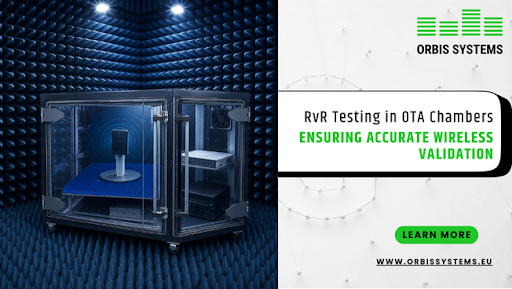
This article explains the key changes that RF test labs should understand and how they can prepare for the next stage of wireless testing, including the growing importance of RVR Wi-Fi testing in supporting repeatable wireless performance evaluation.
Key Takeaways
- Wi-Fi 7 brings wider channels, Multi-Link Operation, and higher throughput, which increase testing requirements.
- Early planning helps laboratories prepare for future Wi-Fi technologies.
- Automation supports accurate and repeatable RF measurements.
- Wireless validation now includes interoperability, throughput, and mesh network performance.
- Flexible RF test environments make it easier to support future wireless standards.
Why Wi-Fi Testing Is Changing
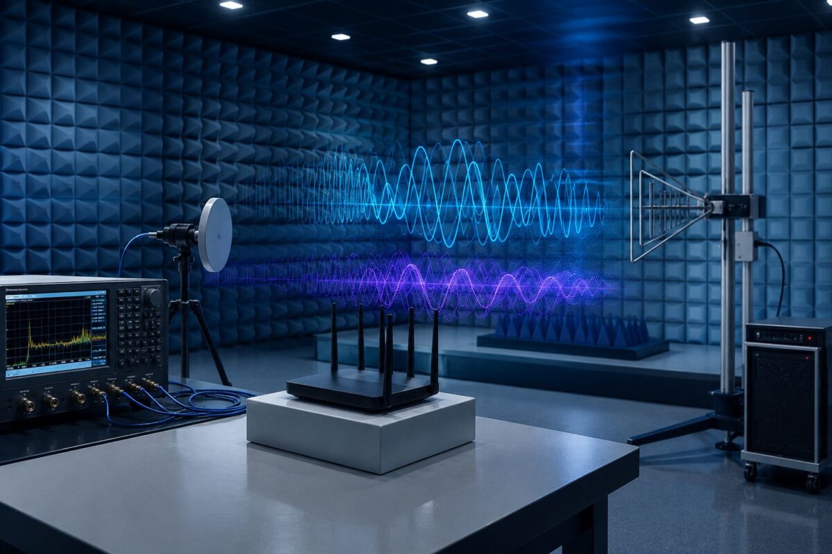
Every new wireless generation introduces new features that improve performance. However, these improvements also make product validation more demanding. Modern wireless devices are expected to deliver fast connections, stable performance, and reliable communication across different environments. Because of this, RF testing now covers much more than basic connectivity.
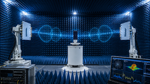
Engineers need to evaluate antenna performance, signal quality, throughput, and device behaviour under different operating conditions. They also need testing environments that provide accurate and repeatable measurements every time. Therefore, Wi-Fi 7 testing has become a key step in product development for many wireless manufacturers.
In addition, many organizations are beginning to review how their current infrastructure can support the future needs of a Wi-Fi 8 RF lab. Planning early allows laboratories to make improvements gradually instead of making major changes later.
Key Testing Areas for Wi-Fi 7
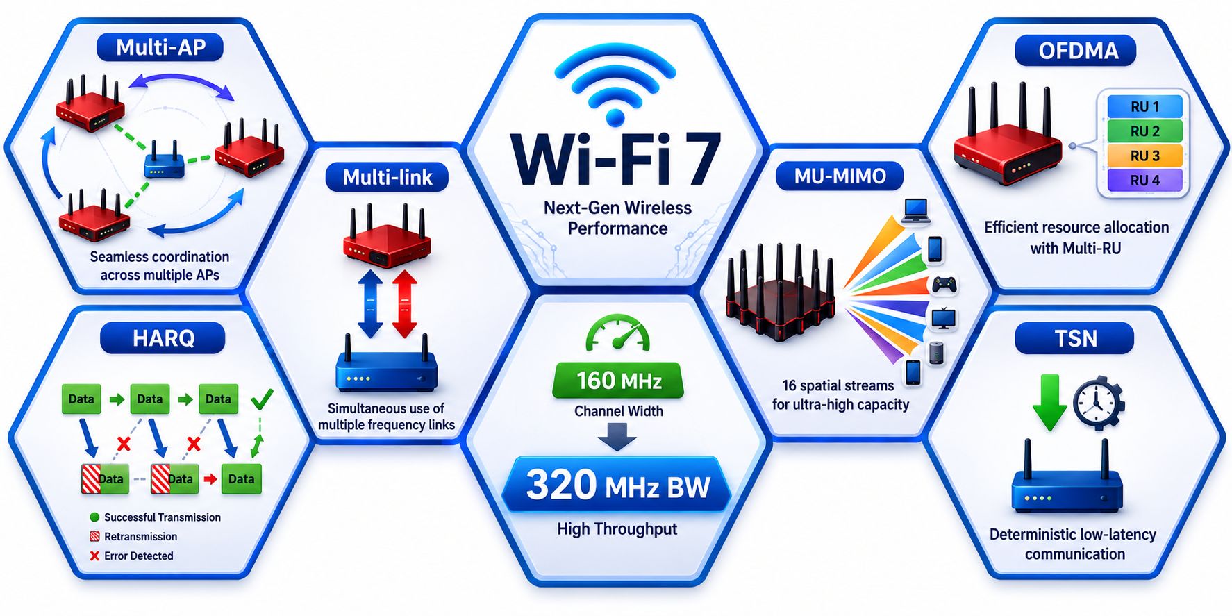
Wi-Fi 7 (IEEE 802.11be) operates across three distinct frequency bands: 2.4 GHz, 5 GHz, and 6 GHz. This tri-band architecture enables backward compatibility with legacy Wi-Fi devices while introducing massive throughput upgrades via the newer, less congested 6 GHz spectrum
Wi-Fi 7 introduces several new capabilities that improve wireless performance. At the same time, these features increase the amount of testing required before products are ready for the market.
Multi-Link Operation Testing
One of the biggest changes is multi-link operation testing. Multi-Link Operation allows a device to send and receive data over more than one wireless link at the same time. As a result, devices can improve speed, reduce delays, and make better use of available wireless resources.
Multi-Link Operation (MLO): Wi-Fi 7 enables clients to aggregate channels across different bands (e.g., using a 320MHz channel in 6GHz while simultaneously linking to 5GHz). Testing MLO ensures both radios work seamlessly to prevent packet drops and lower latency.
However, this feature also means engineers need to confirm that the device performs consistently while managing multiple links together. Testing should be carried out in a controlled RF environment so that measurements remain accurate and repeatable throughout the validation process.
320MHz Channel Testing
Another important requirement is 320MHz channel testing. Wi-Fi 7 supports wider channels than earlier generations, allowing higher data rates where spectrum is available.
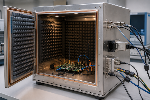
Testing wider channels requires careful control of the RF environment because small changes can affect measurement results. Therefore, laboratories need consistent test conditions throughout the validation process.
Important areas include:
- Stable RF measurement conditions
- Accurate antenna positioning
- Repeatable test results
- Reliable Wi-Fi throughput testing
- Controlled interference levels
In addition, engineers often perform Wi-Fi throughput testing under different operating conditions to understand how devices perform during continuous use rather than only measuring peak speeds.
Looking Ahead to Wi-Fi-8
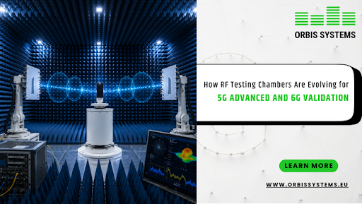
Although Wi-Fi 8 specifications are still being developed, many engineers believe preparation should begin well before products reach the market. Building a Wi-Fi 8 RF lab is not only about supporting higher speeds. It is also about creating a flexible testing environment that can adapt as wireless technology continues to change.
For this reason, laboratories are reviewing their current testing processes, equipment, and automation capabilities. Early planning makes it easier to support future validation requirements without interrupting ongoing development work.
Many laboratories are also focusing on testing methods that improve repeatability, reduce manual work, and support consistent measurement quality across different wireless products.
Why Automation Matters in RF Testing
As testing becomes more detailed, automation plays a larger role in daily laboratory work. Manual testing is still valuable, but it can become time-consuming when engineers need to repeat the same measurements many times.
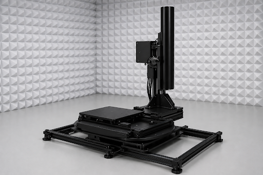
An automated positioning system helps move the device under test in a controlled and repeatable way. Because each measurement is performed from a known position, engineers can compare results more confidently throughout the testing process.
Automation also supports testing efficiency by reducing manual adjustments and helping laboratories complete larger validation programs while maintaining measurement consistency.
Furthermore, repeatable positioning becomes increasingly important as Wi-Fi 7 testing continues to include more advanced wireless features and larger test datasets.
Building a Future-Ready Test Lab
As wireless devices become more advanced, RF laboratories need testing environments that support both current and future technologies. A flexible test lab helps engineers adapt to new requirements without making major changes to the testing process.
An important part of wireless validation is wireless interoperability testing. Devices are expected to work reliably with different access points, client devices, and network configurations. Testing these combinations helps identify compatibility issues before products reach the market.
Mesh network testing is also becoming more important as mesh networks are widely used to improve wireless coverage. Engineers need to evaluate how devices perform while moving between connected access points to better understand real-world performance.
In addition, RVR Wi-Fi testing supports repeatable evaluation of wireless performance under controlled laboratory conditions. It helps engineers compare results across different test scenarios with greater consistency.
Modern RF laboratories also place greater focus on Wi-Fi throughput testing. Engineers need to evaluate not only peak data rates but also how devices perform during longer operating periods and under different traffic conditions.
As wireless technologies continue to evolve, testing requirements will continue to grow. Therefore, many laboratories are preparing their infrastructure to support future wireless standards. Orbis Systems highlights the value of controlled RF environments, accurate positioning, and repeatable measurements through its published RF and OTA testing solutions.
Conclusion
Wireless technologies are becoming more capable with every new generation. As a result, RF validation is also becoming more detailed and more demanding. Features such as wider bandwidth, Multi-Link Operation, and higher throughput require laboratories to perform more comprehensive testing while maintaining accurate and repeatable measurements.
Today, Wi-Fi 7 testing is helping engineers validate products that support these advanced capabilities. At the same time, planning for a Wi-Fi 8 RF lab allows organizations to prepare for future wireless requirements without waiting for new standards to be fully introduced.
A flexible RF testing environment, supported by automation and consistent measurement processes, helps laboratories remain ready for future developments. As wireless technologies continue to progress, Orbis Systems continues to focus on RF testing environments that support accurate and repeatable wireless validation.
Frequently Asked Questions
What is Wi-Fi 7 testing?
Wi-Fi 7 testing is the process of evaluating the RF and wireless performance of devices that support the Wi-Fi 7 standard (IEEE 802.11be) . It includes testing areas such as throughput, channel bandwidth, antenna performance, and wireless communication under controlled laboratory conditions. The goal is to confirm that devices perform reliably before they are released for commercial use.
Why is Multi-Link Operation testing important?
Multi-link operation testing is important because Wi-Fi 7 devices can communicate over multiple wireless links at the same time. Engineers need to verify that these links work together correctly under different operating conditions. Proper testing helps confirm reliable performance, stable communication, and consistent measurement results.
What is involved in 320MHz channel testing?
320MHz channel testing focuses on evaluating device performance across the wider channels introduced with Wi-Fi 7. Engineers assess signal quality, throughput, RF behavior, and measurement consistency while working in a controlled testing environment. Accurate testing helps ensure reliable wireless performance across supported bandwidths.
Why is wireless interoperability testing necessary?
Wireless interoperability testing checks whether a device can communicate correctly with different access points, client devices, and network configurations. This process helps identify compatibility issues before products are deployed and supports reliable performance across different wireless environments.
How can RF laboratories prepare for Wi-Fi 8?
Although Wi-Fi 8 is still under development, laboratories can begin preparing by reviewing their testing infrastructure, improving automation, and building flexible RF environments that support future wireless technologies. Planning early also helps laboratories adapt more efficiently as new testing requirements become available.