Table of Contents
- Why Global Test Equipment Rollouts Are More Complex Than They Appear
- Key Challenges in Multi-Region RF Test Deployments
- Why 24/7 Support Is Critical for Global Test Operations
- Building a Scalable Global Test Equipment Rollout Strategy
- The Role of Engineering Support in Sustaining Long-Term Operations
- Reliable Global Test Operations Require More Than Installation
- Frequently Asked Questions
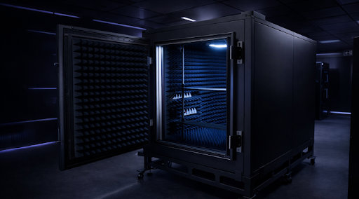
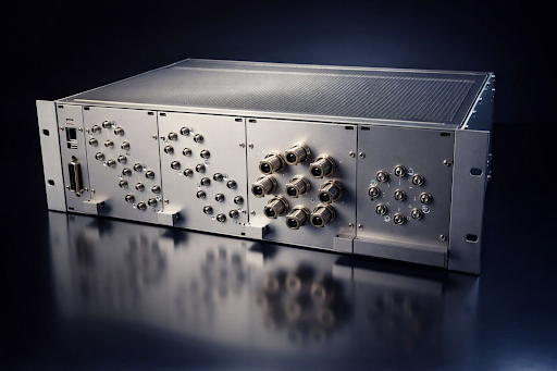
Shipping test systems to multiple locations is only one part of the deployment process. Keeping those systems operational across different regions is another challenge entirely. In telecom and RF environments, testing operations often support validation programs, engineering schedules, and production-related activities where downtime can create delays extending well beyond a single facility.
That is why successful global RF equipment deployment is not limited to installation alone. It requires planning for system consistency, engineering coordination, and continuous support coverage across regions and time zones.
A structured telecom test system rollout should consider the full operational lifecycle from day one. Regional infrastructure, local technical readiness, incident response and escalation processes, remote diagnostics, spare-part availability, and long-term maintenance all influence how effectively a deployed test environment performs once it goes live.

Key Takeaways
- A global RF equipment deployment requires engineering planning, not just installation planning.
- A structured telecom test system rollout helps maintain consistency and repeatability across regions.
- Remote test equipment support can improve system availability and reduce downtime in distributed test environments.
- Telecom engineering support services and RF infrastructure support help reduce operational disruption.
- Custom test equipment, engineering development services, and RF testing solutions can address specialized deployment and validation requirements.
Why Global Test Equipment Rollouts Are More Complex Than They Look
On paper, deploying test systems across multiple sites may appear straightforward. Equipment is designed, shipped, installed, and integrated. In practice, global deployments rarely progress that smoothly.
A site in one region may operate under very different facility conditions than another. Power quality and infrastructure requirements may vary. Installation environments may differ from the original assumptions. Local engineering teams may have varying levels of technical capability and support availability. Even small differences can create delays, increase commissioning effort, or affect system consistency.
That is why a global RF equipment deployment should be managed as an engineering-led program rather than treated only as a logistics exercise.
In RF and telecom testing, consistency matters. A test system should not produce different outcomes across regions because of variations in setup, configuration, calibration, or integration practices. Standardization becomes critical when organizations need reliable and repeatable results across multiple sites.
This engineering-first approach is reflected in companies such as Orbis Systems, where RF test environments, technical integration, and structured deployment methodologies form part of the broader deployment process.
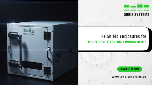
The Real Challenges in Multi-Region RF Deployment
A multi-region RF deployment introduces challenges that are often operational as much as technical.
One of the biggest issues is site variation. Even when the same system is deployed globally, the environment surrounding that system may differ significantly. Facility infrastructure, power quality, environmental controls, network readiness, installation conditions, and local technical resources can all affect integration timelines and deployment outcomes.
Then there is support coverage.
Technical issues do not follow business hours. If a system problem occurs in one region while the responsible support team operates in another time zone, issue resolution may be delayed. In global telecom environments, that delay can affect testing schedules, validation activities, and operational continuity.
System consistency is another common challenge. In global wireless testing operations, small differences in configuration, software versions, calibration status, or test procedures can create larger testing issues later. Engineering teams often spend unnecessary time resolving variation instead of focusing on performance and validation objectives.
Maintenance planning, spare parts coordination, change control, and technical escalation also become more complex as additional sites are introduced.
This is why multi-region RF deployment requires structured planning and lifecycle management from the beginning rather than reactive troubleshooting after deployment.
Why 24/7 Remote Test Equipment Support Matters
Global test environments do not always operate on a single schedule. Engineering teams may work across different regions, and test systems may support validation programs, integration activities, or production-related operations outside standard local working hours.
That changes how support needs to operate.
When a system issue affects an active testing environment, teams may require timely technical support to minimize disruption. Waiting until another regional support team becomes available may not be practical.
A structured remote test equipment support model can help organizations:
- Accelerate issue diagnosis and response
- Reduce downtime across distributed sites
- Improve support continuity across time zones
- Maintain availability in global testing operations
This becomes especially important during a telecom test system rollout and early operational phases, when systems may still require commissioning, technical optimization, performance verification, and operational stabilization after deployment.
In practical terms, support is not only about fixing faults. It is about maintaining testing continuity when multiple regions depend on shared test infrastructure.
This approach is also reflected in RF test environments supported by companies such as Orbis Systems, where engineering coordination and technical support contribute to broader operational performance.
Building a Rollout Strategy That Can Scale
A rollout strategy works best when it can be repeated without introducing additional complexity each time a new site is added.
That means standardization needs to be built into the deployment process.
Consistent system architecture helps reduce variation between locations. Engineering teams can troubleshoot more efficiently when systems follow validated and controlled configurations rather than site-specific custom implementations.
Some deployment environments, however, may require more specialized solutions. Certain projects may depend on custom test equipment or application-specific test configurations to meet unique testing requirements. In those situations, structured engineering development services can help align system design with project objectives while maintaining deployment consistency.
Integrated RF testing solutions can also help organizations maintain standardized and repeatable testing environments across multiple sites instead of creating fragmented deployment models.
Scalability is not simply about adding more locations. It is about ensuring that each additional site can be deployed, operated, and supported without increasing operational risk or support complexity.
That structured approach is one reason engineering-led deployment planning remains important in complex RF and telecom test environments, including technical applications addressed by Orbis Systems.
The Role of Telecom Engineering Support in Long-Term Operations
Deployment does not end when a system is installed.
Global testing environments often require continued technical oversight after installation. System validation, configuration optimization, issue escalation, integration updates, maintenance coordination, and performance troubleshooting may continue long after deployment is complete.
This is where telecom engineering support services become part of ongoing lifecycle and operational planning.
Engineering support often contributes to:
- Technical troubleshooting
- System commissioning and validation
- Ongoing RF infrastructure support
- System integration and change coordination
- Operational continuity across sites
Some projects may also require custom test equipment, integrated RF testing solutions, or specialized engineering development services, depending on testing requirements, validation objectives, and deployment complexity.
Companies such as Orbis Systems work in technical areas where RF test systems, engineering integration, and structured testing environments contribute to broader long-term operational support.
Reliable Global Test Operations Depend on More Than Installation
Global test equipment rollouts succeed when organizations plan for what happens after deployment, not only during it. System consistency, configuration control, engineering coordination, issue response, maintenance readiness, and long-term operational support all influence how effectively global testing environments perform.
As testing programs expand across regions, deployment strategies need to prioritize operational availability and support readiness alongside installation execution. A well-managed rollout supported by technical planning, structured remote test equipment support, and reliable RF infrastructure support can help organizations maintain continuity across global operations.
That engineering-led approach remains central in complex RF environments, and it aligns with the structured test system focus seen in companies such as Orbis Systems, where RF testing, engineering integration, and controlled test environments support broader global deployment requirements.
Frequently Asked Questions
1. What is global RF equipment deployment?
Global RF equipment deployment refers to deploying, integrating, operating, and supporting RF test systems across multiple geographic regions while maintaining technical consistency, repeatable performance, and operational reliability.
2. Why is 24/7 support important in global test rollouts?
Global testing environments often operate across multiple time zones, so timely technical support can help reduce downtime and maintain operational continuity.
3. What are the common challenges in multi-region RF deployment?
Infrastructure variation, support coordination, configuration control, system standardization, maintenance logistics, and technical escalation are common challenges in multi-region RF deployments.
4. How does remote test equipment help engineering teams?
Remote test equipment support helps engineering teams accelerate diagnostics, improve response times, and reduce operational disruption across distributed test environments.
5. Why is RF infrastructure support important in telecom testing?
RF infrastructure support helps maintain system availability, reduce operational downtime, and support consistent test performance across global testing operations.