Table of Contents
- Why Modern Labs Need Flexible RF Test Setups
- Understanding Modular Chamber Design
- Benefits of Adaptable Testing Environments
- Supporting Lab Scalability Solutions
- Readiness for 6G and Future Technologies
- Frequently Asked Questions
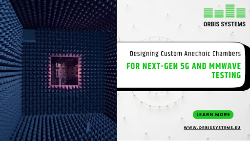
Why Modern Labs Need Flexible RF Test Setups
Wireless technology continues to accelerate. Devices are becoming more complex, and frequency bands are expanding into mm Wave and emerging sub-THz ranges. As a result, laboratories must adjust their RF chamber testing setups more often than before. Traditional fixed chambers can limit flexibility and increase upgrade costs. Therefore, many organizations are adopting modular chamber design to create adaptable testing environments that can evolve with changing requirements.
A future-ready laboratory must support emerging standards, advanced antenna architectures, and higher frequency operation while maintaining measurement accuracy and repeatability. Modular approaches provide practical lab scalability solutions by using standardized shielding panels, absorber systems, and configurable layouts. This allows laboratories to expand or reconfigure test setups without reconstructing entire facilities.
Key Takeaways
- Modular chamber design allows laboratories to adjust layouts and capabilities without full structural reconstruction.
- Adaptable testing environments improve flexibility, reduce downtime, and maintain measurement consistency.
- Lab scalability solutions enable smooth expansion from research to production.
- Modular RF chambers support automation and integration with manufacturing and integration systems.
- Structured modular architecture helps laboratories prepare for 6G and future technologies.
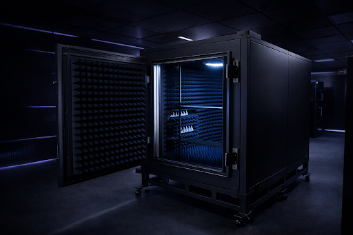
Understanding Modular Chamber Design
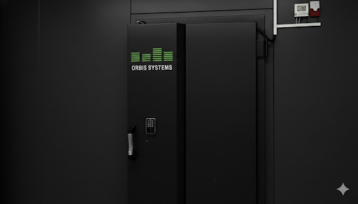
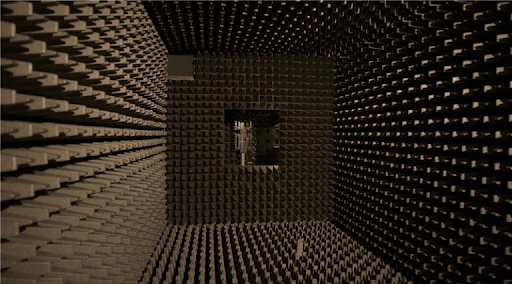
Modular chamber design refers to constructing RF test chambers using standardized shielding panels, absorber modules, and configurable positioning systems that can be assembled according to specific test requirements. Unlike monolithic enclosures with fixed dimensions, modular systems allow expansion, reconfiguration, or targeted upgrades while maintaining shielding integrity and absorber performance.
For example, absorber materials can be replaced to support new frequency ranges, and shielded panel structures can be extended to accommodate larger devices or test distances.
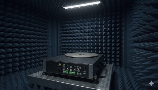
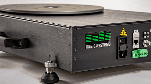
Positioning systems may also be upgraded to support different antenna orientations or multi-axis motion required for advanced OTA measurements. This modular architecture provides a controlled electromagnetic environment while enabling gradual modification as requirements evolve.
In addition, standardized modular designs promote consistency across multiple installations. When similar chambers are deployed across different laboratories, measurement conditions remain comparable, improving repeatability from early development through production validation.
Benefits of Adaptable Testing Environments
Adaptable testing environments provide both operational and technical advantages. Modular components can be upgraded or replaced individually, reducing downtime compared with full chamber reconstruction. This approach also lowers long-term costs by enabling incremental investment aligned with evolving requirements.
Key advantages include reconfigurable layouts that accommodate different device sizes, antenna patterns, and test distances; consistent shielding effectiveness across configurations; precision positioning systems for repeatable OTA measurements; and integration capabilities with automated test systems via standard control interfaces.
In addition, adaptable environments enable laboratories to respond quickly to updated regulatory or certification requirements. Modules can be modified or upgraded without major disruption, helping maintain development schedules. Modular architecture also supports clear configuration documentation and traceability, which are essential for quality assurance, compliance, and multi-site testing consistency.
Supporting Lab Scalability Solutions
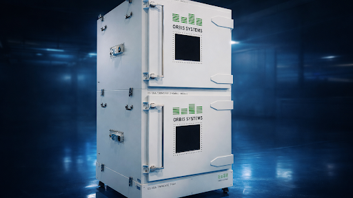
Laboratories often begin with a small development setup and later expand into production testing. For this reason, lab scalability solutions are critical. Modular RF chambers allow gradual growth without replacing existing infrastructure.
In early development stages, a compact chamber may be sufficient for antenna validation and basic RF chamber testing. However, when product volumes increase, additional chambers can be installed using the same modular architecture. This ensures similar electromagnetic performance across all units.
Key aspects that support scalability include:
- Parallel chamber deployment with identical module configurations
- Automation readiness for integration with manufacturing integration systems
- Standardized positioning platforms for high throughput testing
Modular RF chambers support scalable laboratory growth by enabling replication of electrically equivalent test environments across development and production stages. During early R&D, a compact chamber may suffice for antenna validation and basic RF testing. As product volumes increase, additional chambers can be deployed using identical modular configurations, ensuring consistent shielding effectiveness, quiet zone characteristics, and measurement correlation.
Scalability is further supported by automation-ready positioning systems and standardized control interfaces such as SCPI and REST APIs, allowing seamless integration with manufacturing execution systems and automated test equipment. This modular architecture simplifies phased facility expansion, reduces planning risk, and enables controlled budget allocation while maintaining consistent test workflows from R&D to full-scale manufacturing.
Readiness for 6G and Future Technologies
The transition from 5G to 6G introduces new frequency ranges including mmWave extensions and emerging sub-THz bands, along with significantly higher performance requirements. Laboratories must therefore prepare for future technologies without repeated structural reconstruction. Modular chamber design provides this flexibility.
By selecting absorber materials and shielding systems that support wide frequency coverage, laboratories can accommodate both current and emerging standards. If requirements evolve, specific modules can be upgraded while the primary chamber structure remains intact.
Adaptable testing environments also support advances in antenna technology. As beamforming, massive MIMO, and advanced array systems become more prevalent, positioning systems must deliver precise and repeatable motion control for accurate OTA measurements. Modular chambers allow these motion systems to be upgraded or replaced as needed.
This flexibility helps organizations protect long-term investments while remaining ready for 6G research, validation, and future wireless technologies, supporting sustainable scalability aligned with long-term technology roadmaps.
Frequently Asked Questions
What is modular chamber design in RF testing?
Modular chamber design is a method of constructing RF chambers using standardized and configurable components. These components include shielding panels, absorber systems, and positioning systems. Because the system is modular, laboratories can expand or reconfigure the chamber as requirements change. This approach maintains controlled electromagnetic conditions while allowing flexibility.
How do adaptable testing environments improve efficiency?
Adaptable testing environments allow laboratories to adjust layouts and hardware without full reconstruction. As a result, upgrade cycles are shorter and operational downtime is reduced. In addition, standardized modules maintain consistent shielding performance and repeatable measurement conditions.
Can modular RF chambers support manufacturing and integration needs?
Yes. Modular RF chambers can be integrated with automated test equipment and control systems. Interfaces such as REST APIs and SCPI enable communication between chamber control systems, positioning equipment, RF instruments, and laboratory software platforms.
How do modular chambers help with lab scalability solutions?
Modular chambers allow gradual expansion. Laboratories can start with a single chamber and later deploy additional units using identical modules. Because configurations remain consistent, measurement results stay comparable across multiple test stations.
Are modular chambers suitable for 6G testing?
Modular chambers can be configured to support wide frequency ranges, including bands associated with 5G and emerging 6G research. When new frequency requirements arise, absorber materials or positioning systems can be upgraded. Consequently, laboratories can prepare for future technologies without rebuilding their facilities.