Table of Contents
- What Makes Wi-Fi 7 RvR Testing Different?
- Setting Up the Test Without Introducing Measurement Errors
- Equipment Selection: Where Accuracy Really Comes From
- Which Measurements Should Go Into the Test Report?
- Five Mistakes That Can Make RvR Results Misleading
- Preparing the Laboratory for More Demanding Wireless Tests
- Looking Beyond Peak Throughput
- Frequently Asked Questions
A wireless device does not stop working the moment its signal gets weaker. What changes first is usually its data rate, modulation scheme, or transmission reliability. For a manufacturer, knowing exactly when these changes occur can make the difference between a product that performs well in laboratory conditions and one that meets its coverage requirements in deployment.
This is the problem that RvR Wi-Fi testing helps investigate. Rate vs Range (RvR) measurements show how throughput responds to changing RF conditions. With Wi-Fi 7, the exercise has become more involved because engineers must account for wider channels, multiple links, and higher order modulation.
The challenge is not simply to record the highest data rate. It is to understand what happens when the connection is no longer operating under ideal conditions.
Key Takeaways
- RvR measurements reveal throughput changes at different received signal levels.
- Channel bandwidth and modulation are two Wi-Fi 7 parameters that need to be carefully monitored during testing.
- Attenuation calibration and antenna positioning accuracy directly affect measurement precision.
- Automation makes wireless validation more reproducible across runs, firmware versions, and hardware revisions.
- Radiated device performance can be investigated through OTA environments under controlled conditions.
- Link level MLO measurements matter as much as aggregate throughput for Wi-Fi 7 validation.
What Makes Wi-Fi 7 RvR Testing Different?
Wi-Fi 7, standardized under IEEE 802.11be, supports channel bandwidths up to 320 MHz, 4096-QAM, and Multi-Link Operation (MLO). These capabilities allow higher data transfer rates, though the extent to which those advantages can be realized depends on the actual channel conditions.
Consider a device operating with 4096-QAM. It can achieve high spectral efficiency when the received signal has sufficient quality. As interference increases or signal strength falls, maintaining that modulation becomes difficult. The device may move to a lower modulation and coding scheme, reducing throughput.
This is precisely where wireless RvR testing becomes useful. As Wi-Fi 7 adoption continues to grow across consumer and enterprise devices, repeatable wireless validation becomes increasingly important for manufacturers who need to demonstrate consistent coverage and throughput behavior.
Setting Up the Test Without Introducing Measurement Errors
A typical RvR arrangement consists of a reference access point, a Device Under Test (DUT), RF control equipment, and a traffic measurement platform.
The first decision is whether the test will use a conducted or radiated configuration. Conducted testing provides greater control over the RF path, while OTA testing includes antenna characteristics and radiated behavior.
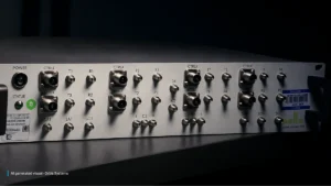
To control signal variation, an RF programmable attenuator introduces predefined losses between the transmitter and receiver. The attenuation is set in known steps, allowing engineers to measure throughput at each step without physically moving the DUT.
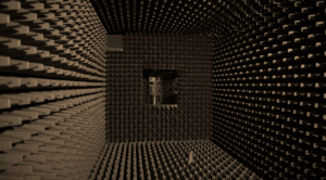
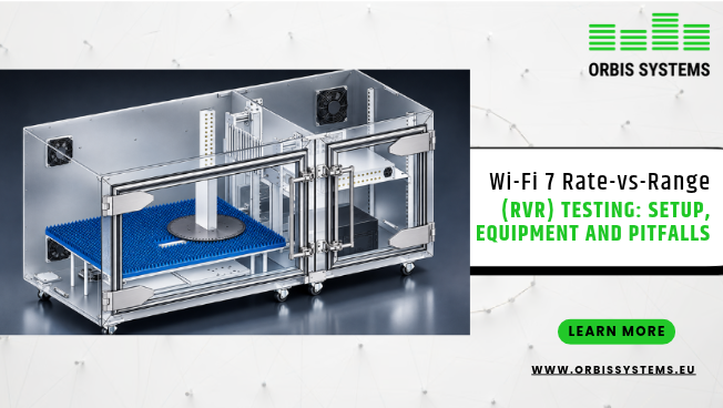
An RF shielded box helps isolate the setup from external transmissions. For radiated measurements, RvR testing in OTA chambers offers a controlled environment where antenna orientation and propagation conditions can be examined.
Before starting, record the DUT firmware, channel width, operating frequency, transmit power, antenna arrangement, and traffic configuration. Changing any of these midway through a test can make comparisons unreliable.
Equipment Selection: Where Accuracy Really Comes From
The specifications on an instrument datasheet do not tell the whole story. Its performance must also suit the measurement path.
Attenuation and RF Control
An RF programmable attenuator should cover the required frequency bands and provide suitable attenuation resolution. Engineers should account for insertion loss, return loss, switching repeatability, and power handling.
One practical precaution is to characterize the complete RF path before testing. Cable and connector losses can otherwise be mistaken for attenuation introduced by the test instrument.
Shielding and Radiated Measurements
An RF shielded box is useful when external interference needs to be excluded from a controlled measurement. However, it does not automatically reproduce an OTA environment.
For antenna evaluation, RvR testing in OTA chambers allows engineers to study radiated performance under controlled conditions. Chamber size, absorber performance, antenna separation, and positioning accuracy all influence the results.
Automation and Instrument Coordination
Running the same attenuation sequence manually across several frequency bands can become tedious. More importantly, it creates opportunities for inconsistent settings and recording mistakes.
Well integrated automated test systems coordinate RF switching, instrument control, positioning, and data acquisition. They also make it easier to repeat a test after a firmware update or hardware modification.
Which Measurements Should Go Into the Test Report?
A throughput graph is useful, but it should not be the only output from an RvR campaign.
Engineers should examine the following parameters together:
- Throughput: Actual uplink and downlink data rates at each signal level.
- RSSI: Received signal strength, useful for correlating throughput changes with attenuation.
- PER: Packet error rate, which indicates how reliable the transmission is.
- Latency: How packet delays vary as radio conditions deteriorate.
- MCS: Modulation and coding scheme transitions during the test.
- MLO behavior: Link availability, traffic distribution, and switching behavior.
For Wi-Fi 7 testing, MLO deserves particular attention. A device may still show good aggregate throughput even when one of its interfaces has been degraded for some time. Recording individual link performance alongside aggregate results gives engineers a clearer picture.
The same measurement discipline is useful in mesh network testing, where backhaul quality and node connectivity can influence overall network performance.
Five Mistakes That Can Make RvR Results Misleading
Some testing problems are easy to miss because the equipment keeps producing numbers. The question is whether those numbers represent the DUT’s actual performance.
- Changing the antenna position between runs: A small variation in direction can change the radiation pattern and therefore the received power level. Antenna position changes should always follow documented procedures.
- Treating attenuation as physical distance: Adding attenuation is a convenient way to simulate additional path loss, but it is not a perfect replica of real propagation. Reflections, obstacles, and multipath effects should be considered separately.
- Ignoring calibration drift: Instrument settings staying the same does not guarantee that the actual RF levels have stayed the same. Cable losses, connectors, and calibration should be checked before each measurement campaign.
- Testing MLO only as an aggregate connection: This approach can hide problems affecting individual links. Link level statistics should be recorded separately.
- Relying entirely on manual measurements: The variation introduced by manual reconfiguration makes this impractical for serious validation work. Validated automated test scripts run the same sequence consistently across repeated measurements.
Preparing the Laboratory for More Demanding Wireless Tests
A test environment should accommodate more than one product configuration. Today’s Wi-Fi 7 router may require different antenna arrangements and channel settings from the next hardware revision.
This engineering led approach is reflected in companies such as Orbis Systems, where RF and OTA testing solutions for demanding wireless validation requirements are developed with a modular approach that supports changing development and production needs.
Combining an RF programmable attenuator, appropriate chamber configurations, and automated test systems gives manufacturers a more controlled way to investigate wireless performance. This infrastructure can also support mesh network testing and other RF validation activities.
For companies expanding their RvR Wi-Fi testing capabilities, the ability to reuse and adapt laboratory equipment is worth considering from the beginning.
Looking Beyond Peak Throughput
A strong peak throughput result is only one part of wireless product validation. The more useful question is how consistently a device performs when signal conditions change.
A properly documented wireless RvR testing procedure helps answer that question. By examining modulation changes, packet errors, latency, and link behavior, engineers can identify limitations that a simple throughput test might overlook.
As adoption grows, Wi-Fi 7 testing will require reliable measurements across increasingly complex configurations. This structured approach is aligned with the direction taken by companies such as Orbis Systems, where RF and OTA testing technologies are developed for evolving wireless requirements across development and production environments.
Frequently Asked Questions
1. What is the main purpose of RvR testing?
RvR testing measures how device throughput degrades as the received signal strength decreases. Engineers use the results to identify coverage limits and performance boundaries in wireless products.
2. Can attenuation replace physical distance measurements?
No. Attenuation provides consistent signal loss that can be reproduced in the lab, but physical distance also introduces propagation effects such as reflections and multipath that attenuation alone cannot replicate.
3. Why are OTA chambers useful for Wi-Fi 7 validation?
OTA chambers provide a controlled environment for radiated testing, which allows engineers to evaluate antenna performance and wireless connectivity while minimizing outside interference.
4. How does MLO influence RvR results?
Multi-Link Operation allows a device to operate across multiple wireless links at the same time. Engineers should record per link performance alongside aggregate throughput, since problems on one link can be hidden by strong performance on others.
5. What role does automation play in RvR testing?
Automation configures instrument settings, steps attenuation values, and records measurements consistently across runs. This improves reproducibility and simplifies comparison between test cycles, firmware builds, and hardware revisions.