Table of Contents
- What Happens During an OTA Test?
- Four RF Measurements Engineers Need to Understand
- Total Radiated Power (TRP)
- Total Isotropic Sensitivity (TIS)
- Effective Isotropic Radiated Power (EIRP)
- Effective Isotropic Sensitivity (EIS)
- What Makes an OTA Testing Environment Reliable?
- Why Automation Matters in Modern RF Testing
- Choosing the Right Infrastructure for Future Testing
- Building Confidence in the Next Generation of Wireless Devices
- Frequently Asked Questions
Here is a situation engineers run into more often than they would like. A wireless device passes its conducted RF test with no trouble, then underperforms once the antennas are actually working. The reason is straightforward. A cable connection shows how a transmitter or receiver behaves at one particular test port, and that is all it shows. It cannot capture the whole picture, especially once antenna placement, device orientation, enclosure materials, and signal direction start to matter.
Over the Air (OTA) testing closes that gap. Rather than relying on direct connections to the antenna ports, it examines how a device actually radiates and receives RF signals. For teams building smartphones, connected vehicles, IoT equipment, or 5G hardware, these measurements provide valuable information long before the product reaches production.
The controlled environment for all of this is an OTA test chamber. Inside it, engineers commonly look at four measurements: Total Radiated Power (TRP), Total Isotropic Sensitivity (TIS), Effective Isotropic Radiated Power (EIRP), and Effective Isotropic Sensitivity (EIS).
Key Takeaways
- OTA testing evaluates the radiated performance of a complete wireless device.
- TRP and TIS describe overall transmission and reception performance.
- EIRP and EIS help characterize directional RF behavior.
- Chamber design and accurate positioning directly influence measurement reliability.
- Automation makes complex RF validation sequences easier to repeat and manage.
- Modular chamber and switching architectures help laboratories scale as test requirements evolve.
What Happens During an OTA Test?
The setup is fairly straightforward. Engineers place the Device Under Test (DUT) inside a shielded measurement environment. Test antennas communicate with the DUT, and RF instruments capture whatever it transmits or receives.
The DUT does not stay in one position. It is examined at different orientations so engineers can understand how its antenna system behaves across multiple directions. Depending on the test configuration, they may also evaluate beamforming, MIMO performance, throughput, and receiver sensitivity.
The sheer scale of wireless connectivity makes this validation more relevant every year. With billions of wireless connections worldwide and 5G rollouts continuing to expand, radiated performance measurements are no longer optional for teams developing competitive wireless products.
A well designed OTA test chamber keeps outside interference and unwanted reflections from distorting these measurements. Depending on its configuration, a 5G OTA chamber can also handle testing across Sub-6 GHz (FR1) and millimeter wave (FR2) frequency ranges.
Four RF Measurements Engineers Need to Understand
TRP, TIS, EIRP, and EIS are usually mentioned together, but they are not interchangeable. Each one answers a different engineering question.
1. Total Radiated Power (TRP)
How much RF power does the complete device actually radiate?
That is the question TRP answers. It measures the total power emitted across the entire radiation sphere. Conducted output power leaves out the effects of antenna efficiency, impedance matching, and device integration, whereas TRP captures them.
In practice, engineers collect measurements at multiple angular positions and then integrate the results to estimate the total radiated power.
Take a smartphone whose transmitter delivers the expected power at its RF port. On paper, everything looks fine. However, poor antenna efficiency or losses introduced by the enclosure can still pull the radiated output down. TRP is what reveals that difference.
For this reason it is an important parameter in UE performance testing, particularly when the subject is a complete device rather than an individual RF component.
2. Total Isotropic Sensitivity (TIS)
TRP looks at transmission. TIS covers the other side of the communication link, which is reception.
It measures a device’s overall receiving sensitivity across different directions. The antenna system and the receiver are considered together, so the assessment is more representative than a direct conducted sensitivity measurement would provide.
Lower is better here. A lower TIS value generally indicates better sensitivity, because the device can receive weaker signals and still meet the specified performance criteria.
For development teams, TIS results can expose reception problems linked to antenna placement, enclosure design, or device orientation.
3. Effective Isotropic Radiated Power (EIRP)
EIRP represents the transmitted power an ideal isotropic antenna (one that distributes its power equally in all directions in 3D space) would need to match the actual radiated power of a real antenna in a particular direction.
The calculation takes into account transmitter output power, directional antenna gain, and any relevant RF losses.
The measurement is especially useful for systems that depend on directional transmission. A 5G device using beamforming, for example, may produce different EIRP values as its active beam changes direction.
Engineers use these results to examine transmission characteristics and verify that the device meets its intended RF performance requirements.
4. Effective Isotropic Sensitivity (EIS)
EIS evaluates a device’s receiving sensitivity for one specific direction of incoming radiation.
Compare that with TIS, which represents overall sensitivity across all directions. EIS provides a directional view of receiver performance instead.
The distinction matters most when testing devices with beamforming antennas. One direction may produce excellent reception while another angle gives noticeably weaker results.
EIS measurements help pinpoint those variations. Together with EIRP, they provide a more detailed understanding of directional transmission and reception during UE performance testing.
What Makes an OTA Testing Environment Reliable?
The specifications of an RF analyzer are only one part of measurement quality. Reflections, external interference, inaccurate positioning, and inconsistent test configurations can all affect results, sometimes more than people expect.
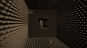
A 5G OTA chamber addresses these issues through RF shielding and absorber lined interiors. The absorbers reduce unwanted reflections, and the shielded enclosure limits interference from outside signals.
A few other components also contribute to measurement accuracy:
- Antenna positioning: An automated positioning system moves the device under test or the measurement antenna through several defined angular positions.
- Flexible configurations: Modular RF chambers allow laboratories to adapt their testing environments to different device sizes and applications.
- Large scale deployment: A sea container OTA chamber provides a dedicated RF testing facility for applications that need a larger or relocatable installation.
This engineering led approach is reflected in companies such as Orbis Systems, where chamber solutions support Sub-6 GHz and mmWave testing with integrated positioning and automation options. These platforms are designed to adapt to the needs of research and development lab spaces as well as mass production facilities.
Why Automation Matters in Modern RF Testing
Consider a team that needs to validate several wireless devices. Each has a different antenna configuration and its own frequency requirements, and every configuration may call for a separate measurement sequence. Handling all those changes manually slows testing down and can introduce inconsistencies.
This is where OTA testing automation becomes useful.
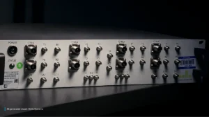
With a software controlled setup, one system can coordinate DUT movement, RF instrument configuration, signal acquisition, and result recording. Programmable signal switching units make RF routing between test instruments, antennas, and devices under test much simpler.
There is another benefit. When chamber hardware, positioning equipment, and switching technology are combined into integrated RF test solutions, it becomes easier to keep test configurations consistent as validation requirements expand.
Choosing the Right Infrastructure for Future Testing
Before investing in testing equipment, engineering teams should establish what their validation program actually requires.
Start with the frequency bands and measurement parameters the DUT must support. From there, consider chamber dimensions, absorber performance, positioning accuracy, instrument compatibility, and software integration.
Requirements also differ by application. A 5G OTA chamber selected for smartphone testing, for instance, may need different positioning and measurement capabilities from a setup intended for automotive connectivity or base station validation.
Scalability deserves equal attention. Modular RF chambers and compatible automation hardware can help laboratories accommodate new test configurations without replacing their entire infrastructure.
Building Confidence in the Next Generation of Wireless Devices
Individual component measurements cannot show how a complete wireless device performs through its antenna system. OTA testing can. TRP, TIS, EIRP, and EIS each reveal a different aspect of that performance, from total radiated power and overall sensitivity to the directional behavior of beamforming devices. Together, they provide engineers with a realistic view of how a product will behave once it leaves the lab and reaches real users.
Wireless architectures keep growing more complex, so reliable measurements will depend more and more on controlled environments and repeatable procedures. Investing in the right OTA test chamber, positioning hardware, and automation can help manufacturers identify performance issues earlier and stay confident throughout product development.
Whether the goal is UE performance testing for handsets or validation in a 5G OTA chamber, a well planned setup keeps results consistent. This structured approach is aligned with the direction taken by companies such as Orbis Systems, where chamber technologies, positioning equipment, and RF switching capabilities are developed as part of integrated RF test solutions for demanding wireless testing applications.
Frequently Asked Questions
1. What is the main purpose of OTA testing?
OTA testing measures how a wireless device transmits and receives radio frequency signals through its complete antenna system. This provides a realistic view of radiated performance that cannot be captured by conducted measurements at individual test ports.
2. What is the difference between TRP and TIS?
TRP (Total Radiated Power) measures the total RF power a device radiates across all directions. TIS (Total Isotropic Sensitivity) measures a device’s overall receiving sensitivity across all directions. Both are important for a complete assessment of wireless communication performance.
3. Can OTA testing be used for mmWave devices?
Yes. OTA chambers and measurement systems designed for mmWave testing support directional antenna evaluation and beamforming measurements. The complete setup should be matched to the frequency range and measurement requirements of the intended test.
4. How does automation improve OTA measurements?
Automation coordinates device positioning, RF routing, and measurement acquisition. This reduces repetitive manual operations and makes complex test sequences easier to reproduce across devices, configurations, and development stages.
5. What should manufacturers consider when selecting an OTA chamber?
Frequency coverage, RF isolation, absorber performance, positioning accuracy, and software compatibility are all important factors. The chamber should also suit the device types and measurement requirements of the testing program, whether that means an OTA test chamber for handset work, a 5G OTA chamber for beamforming devices, or a setup built around UE performance testing across multiple product lines.