Table of Contents
- Define the Testing Requirements
- Assess the Site
- Prepare the Site Infrastructure
- Install and Connect the Chamber
- Integrate RF Equipment and Switching
- Configure Positioning and Automation
- Calibrate and Commission the System
- Prepare for Long-Term Operation
- Bringing Controlled OTA Testing to Remote Sites
- Frequently Asked Questions
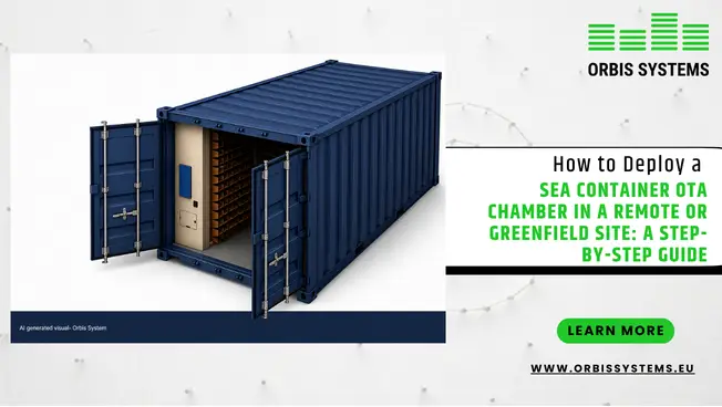
Deploying a sea container OTA chamber at a remote or greenfield site can bring controlled wireless testing to locations where building a permanent test facility is not practical. The process, however, involves more than delivering the container.
The site needs suitable foundations, power, grounding, network access, and RF connections, followed by equipment integration, calibration, and commissioning. Planning these stages in the right order helps create a reliable OTA test chamber that is ready for R&D or production testing.
This guide walks through the deployment sequence step by step, from initial requirement definition through long-term operation.
Key Takeaways
- A sea container OTA chamber can bring controlled OTA testing to remote and greenfield locations.
- Site access, foundation, power, grounding, and network connectivity all need to be prepared before delivery.
- The surrounding RF environment should be assessed before installation to identify possible interference sources.
- RF equipment, positioning systems, and signal switching units are best designed as part of the complete test system.
- Calibration, verification, and commissioning are essential for repeatable measurements over the long term.
- Future frequency, equipment, and automation requirements should be considered during the initial design.
1. Define the Testing Requirements
Before choosing where the chamber will go, it helps to establish what it needs to test.
The frequency range is one of the first considerations. A 5G OTA chamber may be required for Sub-6 GHz applications, while some projects may also need mmWave or FR2 capability. The size and weight of the DUT, measurement distance, antenna arrangement, and required test methods all influence the final configuration.
It is also worth considering how the chamber will be used. An R&D team may need flexibility for different prototypes, while a production environment may place more emphasis on repeatability, automation, and throughput.
A useful starting point is defining:
- Frequency band
- DUT dimensions and weight
- Antenna requirements
- Measurement distance
- Positioning requirements
- RF signal paths
- Measurement equipment
- Automation requirements
- Network interfaces
- Future expansion plans
A clear test specification makes later site and system planning much more straightforward.
2. Assess the Site
A remote installation brings practical challenges that may not exist in a conventional laboratory. The first consideration is how the chamber will reach the location. A container requires suitable road access, unloading space, and lifting arrangements. The route should be assessed before delivery rather than discovered when the transport vehicle arrives.
The installation area itself also needs to be suitable for the chamber. Ground conditions, drainage, available clearance, and access for maintenance all matter.
For a greenfield site, these requirements can be included in the original site design. At an existing remote location, some preparation may be necessary.
The surrounding RF environment deserves attention as well. Nearby transmitters, industrial equipment, and other wireless systems can introduce interference. A site that appears isolated may still have a busy RF environment.
3. Prepare the Site Infrastructure
The chamber should arrive at a site that is already prepared for installation. A stable, level foundation is required, with its design based on the selected chamber configuration. Space around the enclosure should allow engineers to make connections and carry out maintenance.
Power requirements also need to be established before delivery. The supply may need to support the chamber, test instruments, positioning equipment, control systems, and other supporting equipment.
Grounding should form part of the electrical planning from the beginning.
Network connectivity is another important consideration. Automated OTA testing can involve communication between the chamber, instruments, positioning systems, and control software. If the system needs to connect with an existing production or laboratory network, those connections should be available before commissioning.
4. Install and Connect the Chamber
Once the site is ready, the mobile OTA test chamber can be delivered and positioned.
The final position should be checked against the installation plan. Door access, service clearance, cable routes, and equipment connections should all be considered before the chamber is secured.
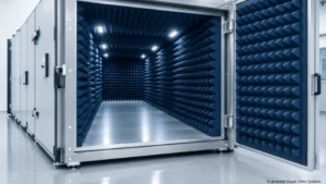
A containerized design brings much of the test environment to the site in one package. The enclosure can incorporate RF shielding and absorber materials to create a controlled environment for OTA measurements.
This is a significant advantage over constructing a conventional chamber entirely on site. It can reduce site work and make deployment more practical at remote locations. The chamber still needs to be installed carefully, particularly where access is limited or specialist support is difficult to arrange.
5. Integrate RF Equipment and Switching
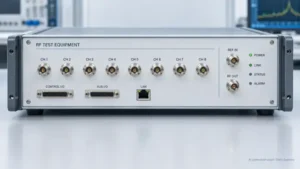
The chamber itself is only one part of the test system. Depending on the application, the setup may include signal generators, analyzers, receivers, antennas, DUT fixtures, positioning equipment, and RF switching hardware.
This is where integrated RF test solutions become useful. Instead of operating each component separately, the chamber and supporting equipment can be configured around the same test process.
Signal switching units can manage connections between RF instruments and the DUT, avoiding the need to change cables by hand when a test requires different signal paths.
A programmable SSU can take this a step further by allowing RF paths to be selected through the control system. This can reduce manual intervention and make repeated test sequences easier to manage.
For production testing, that consistency can make a meaningful difference. Operators can follow a defined test sequence rather than manually rebuilding the RF setup between measurements.
6. Configure Positioning and Automation
OTA measurements depend on controlled positioning.
The DUT needs to be placed at the correct location and orientation, while the antenna may need to move through specific positions or angles. Manual adjustment can work for occasional testing, but automated positioning is more suitable when measurements are repeated frequently.
A portable OTA chamber can incorporate programmable DUT and antenna positioning so that movement becomes part of the test sequence. Automation should also extend beyond physical movement. The positioning system, RF switching, measurement equipment, and software need to communicate correctly.
Depending on the system configuration, interfaces such as REST API, SCPI, and LabVIEW can be used to connect the OTA platform with the wider test environment. This engineering-led approach is reflected in companies such as Orbis Systems, where OTA chamber platforms are designed to integrate with broader test environments rather than operate in isolation.
Each test should be able to run from a known configuration without unnecessary manual adjustment.
7. Calibrate and Commission the System
Before regular testing begins, the complete system needs to be verified.
RF paths should be checked, calibration completed, and the chamber environment assessed. Shielding and absorber performance are important because the purpose of an OTA chamber is to provide controlled measurement conditions.
Repeatability should also be considered. If the same DUT produces different results because its position, RF path, or test configuration has changed, the test environment cannot provide dependable comparison data. This is where structured commissioning services become particularly valuable.
Commissioning can cover installation checks, signal routing verification, calibration, software configuration, performance testing, functional checks, and safety verification.
Factory Acceptance Testing can be completed before delivery, while Site Acceptance Testing verifies the system after installation at its final location. For remote projects, this staged approach can help identify problems before they become expensive site issues.
8. Prepare for Long-Term Operation
Once commissioning is complete, the local team needs to be ready to use the system.
Operators should understand the test sequence, basic equipment checks, positioning controls, and relevant software functions. The final documentation should reflect the installed system and include connection information, operating procedures, and calibration records.
It is also worth considering future requirements.
Wireless testing changes as products and standards develop. Additional frequency bands, higher test volumes, new DUT configurations, or mmWave requirements may arise later. Planning for possible expansion during the original design can make future modifications easier.
Maintenance, calibration, software updates, repairs, and technical support should also be considered as part of the chamber’s operating life.
Bringing Controlled OTA Testing to Remote Sites
Deploying an OTA chamber at a remote or greenfield site requires coordination between the chamber, site infrastructure, and test equipment. A containerized solution reduces the amount of construction required at the destination, but reliable testing still depends on careful installation, RF integration, positioning, calibration, and commissioning.
When these elements are planned as one system, a remote location can support a capable OTA testing environment without requiring the same infrastructure as a permanent laboratory. This structured approach is aligned with the integrated OTA chamber design focus seen in companies such as Orbis Systems, where sea container and mobile OTA chamber solutions are developed alongside supporting engineering, positioning, and commissioning services.
For organizations working with 5G, IoT, telecom, and other wireless technologies, this makes a sea container OTA chamber a practical option for bringing controlled testing closer to the point of development, production, or field deployment.
Frequently Asked Questions
1. What is a sea container OTA chamber?
A sea container OTA chamber is a controlled OTA testing environment built into a shipping-container structure. It can incorporate RF shielding, absorbers, antennas, positioning equipment, and measurement systems. Its containerized format makes it suitable for locations where constructing a permanent OTA facility would be difficult or unnecessary.
2. Can a mobile OTA test chamber be installed at a remote location?
Yes. A mobile OTA test chamber can be deployed at remote sites, provided the location has suitable access, foundations, utilities, and supporting infrastructure. The RF environment should also be assessed to make sure external interference does not affect measurements.
3. Why are signal switching units used in OTA testing?
Signal switching units allow different RF signal paths to be selected without manually reconnecting cables between tests. When integrated with automation, they can make complex test sequences easier to operate and repeat.
4. What is checked during OTA chamber commissioning?
Commissioning can include RF signal routing, calibration, software configuration, positioning, system performance, functional operation, and safety checks. Factory Acceptance Testing and Site Acceptance Testing may also be used to verify the system before delivery and after installation.
5. Can a 5G OTA chamber support future testing requirements?
That depends on the original system configuration. A 5G OTA chamber can be designed around current requirements while allowing suitable provisions for future expansion. Requirements such as additional frequency bands, mmWave testing, new instrumentation, or increased automation are best considered during the initial design stage.