We are creative, ambitious and ready for challenges!

Categories
Blogs Resources

How MU-MIMO Affects Spatial Multiplexing and Test Requirements in 5G Devices

Table of Contents

  1. Understanding Multi-user MIMO Technology
  2. What Is MU-MIMO Spatial Multiplexing
  3. How MU-MIMO Changes 5G Device Test Requirements
  4. Parameters That Must Be Verified
  5. The Role of OTA Testing in MU-MIMO
  6. Challenges in Building MU-MIMO Test Systems
  7. Building Strong Test Methods for MU-MIMO in 5G
  8. FAQs

5G has changed how wireless communication works. It is designed to support high data rates, low latency, and many connected devices. One of the key technologies enabling this is Multi-User MIMO (MU-MIMO). MU-MIMO allows a base station to serve multiple devices simultaneously by spatially separating their signals while using the same time and frequency resources.

In earlier wireless systems, testing mainly focused on single-user performance, since users were largely separated in time or frequency. This made device testing more straightforward, as engineers could evaluate one device in a controlled and static environment. With the introduction of MU-MIMO, multiple devices now operate concurrently, and their signals interact through the spatial domain.

As a result, 5G device testing has become more complex and demanding. Testing must now demonstrate how a device performs in realistic multi-user scenarios, including its ability to maintain stable throughput while sharing radio resources. This involves validating beamforming behavior, signal separation, and interference management.

At Orbis Systems, technical discussions often emphasize the importance of controlled RF environments and repeatable measurements. These factors are critical, as accurate and stable test conditions are essential for reliable MU-MIMO performance evaluation.

How MU-MIMO Affects Spatial Multiplexing and Test Requirements in 5G Devices

Key Takeaways

  • MU-MIMO increases network efficiency but also increases testing complexity.
  • MU-MIMO spatial multiplexing must be validated in real multi-user RF conditions.
  • 5G device test requirements now include multi-user performance and beam accuracy.
  • OTA testing is essential for antenna and beam validation.

Repeatable and stable test setups are necessary for reliable 5G device testing.

Understanding Multi-user MIMO Technology

Multi-user MIMO technology allows a base station to transmit different data streams to multiple devices at the same time. Instead of relying only on time or frequency separation, the system also separates users in the spatial domain.

This is achieved using multiple antennas together with beamforming techniques. Each user is served using a distinct spatial direction or spatial signature, allowing the system to reuse the same radio resources efficiently. As a result, network capacity and spectral efficiency are significantly improved.

While this improves overall network performance, it also increases testing complexity. Devices must be evaluated not only in isolation but also under active multi-user conditions where signals interact. This is one of the key reasons why 5G device test requirements are more advanced compared to earlier generations.

What Is MU-MIMO Spatial Multiplexing

MU-MIMO spatial multiplexing refers to transmitting multiple data streams simultaneously over the same frequency and time resources by exploiting different spatial paths. Beamforming is used to direct energy toward each device while minimizing interference between users.

For effective spatial multiplexing, several factors must be accurately controlled. Antenna patterns must remain stable, beamforming must be precise, channel state information must be accurate, and inter-user interference must be kept low.

If these conditions are not met, overall system performance degrades. Therefore, testing must verify that spatial separation is maintained and that devices continue to perform reliably in shared multi-user RF environments.

How MU-MIMO Changes 5G Device Test Requirements

MU-MIMO introduces a new level of complexity in wireless device testing. Traditionally, engineers focused on signal quality, throughput, and stability for a single device. With MU-MIMO, testing must also evaluate how multiple devices perform simultaneously and interact within the same radio resources.

As a result, 5G device test requirements now include validation of multi-user throughput, beam stability over time, interference management, and result consistency across repeated test runs.

High repeatability is especially critical for MU-MIMO testing. If results vary between measurements, it becomes difficult to draw reliable conclusions about device performance. This makes controlled RF environments essential for accurate testing.

At Orbis Systems, technical materials emphasize the importance of structured test setups that deliver stable and repeatable measurement capabilities that are critical for reliable MU-MIMO validation.

Parameters That Must Be Verified

When testing devices that support MU-MIMO, certain parameters become especially critical. Key metrics include beamforming accuracy, spatial separation between users, SINR, per-user throughput, EVM, and packet error rate.


Together, these measurements indicate how effectively MU-MIMO spatial multiplexing is implemented and help determine whether the device can sustain reliable performance under realistic multi-user network conditions.

The Role of OTA Testing in MU-MIMO

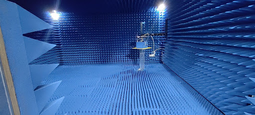
Over-the-air testing is a core component of modern wireless device validation. Because MU-MIMO performance depends heavily on antenna characteristics and beamforming behavior, OTA testing becomes even more critical.

OTA testing is used to measure antenna radiation patterns, verify beam directions, evaluate spatial separation between multiple users, and confirm stable RF performance under realistic conditions.

In addition, OTA environments must accurately represent real radio conditions by allowing signals to arrive from multiple angles, while maintaining a controlled and repeatable test setup.

Within structured 5G device testing workflows, OTA testing supports both early-stage design validation and final product qualification. Orbis Systems emphasizes the importance of stable RF environments that enable accurate and repeatable OTA measurements.

Challenges in Building MU-MIMO Test Systems

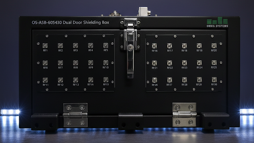
Designing a test system for MU-MIMO is inherently complex and requires careful planning and precise control. Key challenges include synchronizing multiple RF paths, creating accurate and repeatable channel conditions, supporting scalable test configurations, maintaining long-term measurement stability, and ensuring traceable calibration.

To meet evolving 5G device test requirements, test systems must remain flexible. As standards and features continue to expand, new test cases must be supported without redesigning the entire setup. For this reason, modular system architecture is essential.

Orbis Systems emphasizes the importance of modular and repeatable test environments in advanced RF testing, as these principles are fundamental to managing the complexity of MU-MIMO validation.

Building Strong Test Methods for MU-MIMO in 5G

MU-MIMO is a fundamental feature of modern 5G networks, enabling simultaneous multi-user communication and improved spectral efficiency. While these capabilities enhance network performance, they also significantly increase the complexity of device testing.

To meet current 5G device test requirements, validation must closely reflect real network behavior. Devices need to be evaluated in shared radio environments where beamforming, inter-user interference, and spatial separation directly affect performance.

By employing controlled RF environments, repeatable test workflows, and robust OTA testing, engineers can achieve consistent and reliable validation results. Orbis Systems continues to emphasize these testing principles in its technical discussions, supporting a deeper understanding of advanced RF and MU-MIMO validation challenges.

FAQs

1. Why does MU-MIMO make testing more complex than earlier technologies?

MU-MIMO allows multiple devices to use the same frequency at the same time. This creates interactions between signals. As a result, testing must check how a device performs not only on its own but also when other users are active. This adds more test cases and more parameters to verify.

2. How does MU-MIMO spatial multiplexing affect device performance checks?

MU-MIMO spatial multiplexing requires that each user’s signal remain separated in space. Testing must confirm that beams are correctly formed and that interference stays within acceptable limits. Without this, throughput and stability can drop.

3. Why is OTA testing necessary for MU-MIMO validation?

OTA testing evaluates real antenna behavior. Since MU-MIMO depends on beam direction and radiation patterns, OTA testing shows how the device will perform in real wireless conditions. It is not enough to test only through cables.

OTA testing evaluates real antenna behavior. Since MU-MIMO depends on beam direction and radiation patterns, OTA testing shows how the device will perform in real wireless conditions. It is not enough to test only through cables.

4. How do 5G device test requirements change because of MU-MIMO?

5G device test requirements now include multi-user throughput, beam stability, interference control, and measurement repeatability. These areas were less important when devices operated mainly in single-user modes.

5. Why is automation important in 5G device testing for MU-MIMO?

Automation helps keep results consistent. MU-MIMO testing includes many steps and configurations. Automated workflows reduce human error and make results easier to compare. This improves reliability in 5G device testing and supports long-term quality control.

Categories
Blogs Resources

Manual RF Testing vs Automation: Cost, Accuracy, and Scalability

Table of Contents

  1. Why Manual RF Testing Needs a Closer Look
  2. Hidden Technical Issues in Manual RF Testing
  3. How Automation Helps Reduce RF Test Time
  4. Real RF Test Automation Benefits
  5. Why RF Test Automation Is the Practical Way Forward
  6. Frequently Asked Questions

Manual RF Testing vs Automation: Cost, Accuracy, and Scalability

Key Takeaways

  • Manual RF testing becomes slower as testing grows
  • Human involvement introduces variation and rework
  • Manual methods limit scalability and efficiency
  • Automation helps reduce RF test time
  • RF test automation benefits include better consistency and productivity

Why Manual RF Testing Needs a Closer Look

Radio frequency testing is a basic requirement when building and validating wireless devices. It helps teams confirm that a product works correctly and meets expected performance levels. Because RF behavior is sensitive, testing must be done carefully and in a consistent way.

In many engineering teams, manual RF testing is still common. Engineers connect cables, adjust instruments, and run measurements by hand. At the beginning, this approach seems simple and flexible. It also feels easy to control.

However, as projects move forward, the limits of manual RF testing start to appear. Test counts grow. Devices become more complex. Deadlines become tighter. Because of this, manual testing often creates delays instead of supporting progress.

This blog explains the true cost of manual RF testing and why automation is increasingly chosen to reduce RF test time while keeping test results reliable.

Why Manual RF Testing Becomes a Problem

Manual RF testing depends completely on people. Every test requires physical setup. Cables must be connected. Instruments must be configured. Results must be checked manually.

At a small scale, this works. However, as the number of tests increases, the time required also increases. Each new test adds more setup work. Over a full project, these minutes turn into hours and days.

Another issue is repetition. Engineers often repeat the same steps again and again. This work is slow and tiring. Over time, fatigue increases the chance of mistakes.

Errors are another cost. A loose cable or a missed setting can affect results. When this happens, tests must be repeated. This leads to rework and further delays.

There is also hardware wear. Cables and connectors are handled many times. As they wear out, signal behavior changes. This creates unstable readings and more troubleshooting.

Because of all this, manual RF testing often costs more time and effort than teams expect.

Hidden Technical Issues in Manual RF Testing

Manual RF testing also creates technical problems that are easy to overlook.

One issue is inconsistency. Different people may perform the same test slightly differently. Even small changes in how a cable is connected can affect the signal. Because of this, results may not match exactly from one test to another.

Signal stability is another concern. Manual switching can introduce changes in insertion loss and isolation. These changes reduce confidence in the measurements.

Scaling is also difficult. Modern devices support many bands and antennas. Testing every combination manually takes a long time. To save time, teams may reduce test coverage. This increases risk.

Equipment usage is also inefficient. Test instruments may sit idle while setups are changed. As a result, expensive tools are not used to their full capacity.

Over time, these issues slow development and make test results harder to trust.

How Automation Helps Reduce RF Test Time

Automation removes many of the steps that slow down manual RF testing. Instead of relying on physical actions, automated systems use controlled RF switching and predefined test flows.

First, automated switching routes signals in the same way every time. This improves consistency and removes the need to reconnect cables for each test.

Next, test sequences can be created in advance. Once started, tests run without constant attention. Because of this, engineers do not need to stay next to the system.

Automation also allows tests to run in parallel. Multiple measurements can be completed at the same time. This directly helps reduce RF test time.

Another important benefit is continuous operation. Automated systems can run during evenings or weekends. This increases output without increasing staff workload.

Overall, automation allows teams to test more, test faster, and test more consistently.

Real RF Test Automation Benefits

Automation brings practical benefits that go beyond speed.

One benefit is improved repeatability. Fixed signal paths reduce variation between test runs. Results become easier to compare.

Another benefit is fewer errors. When manual steps are removed, mistakes happen less often. This reduces rework.

Automation also helps engineers use their time better. Instead of setting up tests, they can focus on understanding results and solving problems.

As test needs grow, automated systems can scale. More tests can be added without adding the same number of people.

These RF test automation benefits support both development work and long-term testing needs.

Why RF Test Automation Is the Practical Way Forward

Manual RF testing has been used for many years. It works at small scale. However, as testing becomes more complex, manual methods create delays and inconsistency.

Automation offers a better approach. It helps reduce RF test time, improves repeatability, and supports reliable testing over time. By moving away from manual RF testing, teams can work more efficiently while maintaining confidence in their results.

FAQs

1. What is manual RF testing in simple terms?

Manual RF testing means engineers perform each test step by hand. They connect cables, change signal paths, configure instruments, and start measurements manually. Every action depends on a person.

Because people are involved at every step, results can vary. The process also takes more time as test volume increases.

2. Why does manual RF testing slow projects down?

Manual testing slows projects because setup work is repeated for every test. As the number of tests increases, this repeated effort adds up.

Mistakes also happen. When a test must be repeated, more time is lost. Over a full project, these delays become significant.

3. How does manual RF testing affect result reliability?

Manual RF testing makes consistency difficult. Small differences in cable connections or handling can change signal behavior.

Because of this, engineers may see differences in results that are not caused by the device itself. This makes analysis harder and reduces confidence.

4. How does automation help reduce RF test time?

Automation removes manual setup steps. RF switching and test control are handled by software.

Tests can run continuously and in parallel. As a result, more testing is completed in less time with the same coverage.

5. Is automation useful outside high-volume testing?

Yes. Automation is useful during development, validation, and long-term testing.

It improves consistency, reduces rework, and helps teams manage growing test demands without added complexity.

Categories
Blogs Resources

Automating OTA Testing: Essential Methods for Accurate MIMO & Beamforming Validation

Table of Contents

  1. Why OTA Testing Automation Is Important for Modern Wireless Systems
  2. What OTA Testing Automation Means in Practice
  3. Why 5G OTA Testing Is More Complex
  4. Practical Methods Used for MIMO and Beamforming Validation
  5. Core Elements of an OTA Test System
  6. Why Calibration and Repeatability Matter
  7. How Automation Supports Daily Testing Work
  8. What Consistent OTA Testing Automation Achieves
  9. Frequently Asked Questions

Automating OTA Testing: Essential Methods for Accurate MIMO & Beamforming Validation

Key Takeaways

  • OTA testing automation supports stable and repeatable wireless measurements
  • Automated testing is essential for validating MIMO and beamforming performance.
  • Controlled RF environments reduce unwanted signal effects
  • Calibration is required to maintain measurement accuracy
  • Automation improves consistency across test cycles

Why OTA Testing Automation Is Important for Modern Wireless Systems

Wireless devices today depend on antenna performance more than ever before. Technologies such as MIMO and beamforming are no longer optional features. They are part of how 5G systems are designed to work. Because of this, antenna testing must reflect how signals behave in real conditions.

OTA testing automation allows engineers to measure wireless performance through radiated signals instead of cables. This matters because antennas interact with their surroundings. When tests are automated, the same conditions can be repeated again and again. As a result, test results become more reliable and easier to compare over time.

What OTA Testing Automation Means in Practice

OTA testing automation means running over-the-air measurements using systems that do not rely on constant manual input. The device under test is measured through radiated signals. Automation controls movement, orientation, and test order.

Because of this, tests can be repeated without changes in setup. This is important because antenna performance is sensitive to position and direction. Even small differences can affect results. OTA testing automation helps remove these differences and supports stable measurements.

Why 5G OTA Testing Is More Complex

5G devices use multiple antennas at the same time. These antennas interact with each other. Cable testing cannot fully represent this behavior. Therefore, radiated testing becomes necessary.

In addition, antenna behavior changes across different frequencies. Performance also changes when the device is rotated or tilted. Because of this, testing must take place in a controlled space where external signals are blocked. OTA testing provides this control and supports accurate evaluation.

Practical Methods Used for MIMO and Beamforming Validation

Accurate OTA testing automation depends on a small number of essential methods that work together.

Controlled RF Environment

A shielded chamber blocks outside signals. This allows measurements to focus only on the device being tested. Because the environment does not change, results from different test runs can be compared directly. This is important when validating beam patterns and signal direction.

Precision Position Control

Automated positioning systems control how the device and antennas move during testing. This allows measurements to be taken at defined angles. As a result, engineers can see how performance changes with orientation. This is especially useful for beamforming evaluation.

Automated Test Execution

Test steps are defined in advance and executed automatically. This reduces the chance of human error. It also allows large test sequences to run without interruption. Over time, this improves efficiency and data consistency.

Core Elements of an OTA Test System

A standard OTA test system usually includes the following elements:

  • An RF-shielded chamber to isolate the test environment
  • Positioning equipment to control device and antenna movement
  • Measurement instruments connected to control software
  • Interfaces that allow remote test operation

Many test setups rely on a dedicated 5g ota chamber to keep test conditions stable and predictable during automated measurements.

Why Calibration and Repeatability Matter 

Calibration ensures that measurements remain accurate. Without calibration, test results can slowly drift. Therefore, calibration must be performed before testing begins and reviewed.

This approach supports confident validation and helps ensure wireless systems perform as expected before deployment.

Repeatability is just as important. When the same test is run multiple times, the results should match within acceptable limits. Automation helps achieve this by keeping setup conditions the same. As a result, engineers can trust the data they collect during OTA testing automation.

How Automation Supports Daily Testing Work

Automation makes daily testing easier to manage. Tests can be scheduled in advance. Measurements can run without supervision. Data can be collected in a consistent format.

In addition, automated testing allows the same test sequence to be used during different project stages. This helps teams track performance changes. Over time, this leads to better test control and clearer decision-making.

What Consistent OTA Testing Automation Achieves

Consistent testing leads to reliable results. OTA testing automation provides a structured way to evaluate MIMO and beamforming performance under controlled conditions. By combining stable environments, accurate positioning, and repeatable execution, testing teams can reduce costs.

Frequently Asked Questions

1. What is OTA testing automation?

OTA testing automation is the use of automated systems to perform over-the-air measurements. These systems control device position, test order, and measurement timing to ensure repeatable results.

2. Why is OTA testing needed for MIMO systems?

MIMO systems use several antennas at the same time. OTA testing is required to measure how these antennas interact through radiated signals rather than cables.

3. How does beamforming affect testing methods?

Beamforming directs energy in specific directions. OTA testing allows engineers to measure how well these directions are formed and maintained under different orientations.

4. What role does a 5G OTA chamber play?

A 5G OTA chamber blocks external signals and creates a stable RF environment. This allows accurate and repeatable radiated measurements during automated testing.

5. How does automation improve measurement reliability?

Automation reduces manual changes and setup variation. This ensures that tests follow the same steps each time, which improves consistency and trust in results.

Categories
Blogs Resources

Best Practices for Designing RF Switch Matrices in Modern Wireless Labs

Table of Contents

  1. Importance of RF Switch Matrix Design
  2. Key Points for High-Frequency Switching
  3. Selecting the Right Matrix Structure
  4. Power Handling and High-Power RF Switching
  5. Automation and Control Considerations
  6. Installation and Ongoing Validation
  7. Key Takeaways
  8. Frequently Asked Questions

Wireless testing labs today are not simple places. Engineers work with many devices, many frequency ranges, and many test setups. Some tests focus on Sub-6 GHz. Others involve mmWave or OTA testing. Often, more than one device is tested at the same time.

In such conditions, signal routing must remain stable and repeatable. If signal paths change often, test results can change too. This creates confusion and wastes time.

This is where an RF switch matrix becomes important. It allows RF signals to move between instruments and devices without constant cable changes. When done correctly, this improves repeatability and reduces physical handling of test equipment. This article explains how to design RF switch matrices for modern wireless labs in a clear and practical way.

Best Practices for Designing RF Switch Matrices in Modern Wireless Labs

Summary Highlights

  • A well-planned RF switch matrix improves test repeatability
  • High-frequency behaviour must be carefully checked
  • Modular structures support future lab growth
  • Stable RF test routing reduces manual errors
  • Automation and validation are essential for consistent results

Importance of RF Switch Matrix Design

Wireless testing has changed over the years. Earlier, labs worked with fewer bands and simpler devices. Today, the situation is very different. Multiple radios, antennas, and instruments are used together.

Because of this, RF test routing must be reliable. A well-designed RF switch matrix helps engineers keep test conditions the same across repeated measurements. This improves confidence in results.

Another benefit is reduced cable movement. Frequent manual reconnections can damage connectors over time. Centralized switching reduces this risk. Many labs that use modular switching platforms, including those from Orbis Systems, focus on improving test stability while keeping lab operations efficient.

Key Points for High-Frequency Switching

High-frequency testing requires extra attention. Small losses or reflections can affect measurements more than expected.

Engineers should focus on the following:

  • Insertion loss, which should stay as low as possible
  • Isolation, to avoid signal leakage between paths
  • Return loss and VSWR, which affect impedance matching
  • Switching speed, especially for automated testing

A high-frequency switch matrix must perform well across its full frequency range. Testing only at one frequency is not enough. Cable quality, connector type, and adapters also affect performance. Therefore, these parts must be considered as part of the overall RF path.

Selecting the Right Matrix Structure

The internal structure of a switch matrix affects how flexible the system will be in the future. Choosing the wrong structure can limit expansion.

Common structures include:

  • Blocking matrices, suitable for fixed and predictable routing
  • Non-blocking matrices, which allow several paths at the same time
  • Modular matrices, which can grow with changing lab needs

Scalability matters most in R&D and validation labs. New devices and new frequency bands are added regularly. Modular designs reduce the need for complete system changes later. This is one reason modular RF switching solutions from Orbis Systems are often considered for long-term lab setups.

Power Handling and High-Power RF Switching

Not all RF tests use low signal levels. Some tests involve transmitters, power amplifiers, or stress conditions. In these cases, power handling becomes critical.

Designers must review:

  • Continuous power limits
  • Peak power ratings
  • Heat build-up during repeated switching

Using switches beyond their limits can cause unstable readings or hardware damage. A properly rated high-power RF switch is required in such setups. Choosing the right high-power RF switch helps protect both the test system and the device under test.

Automation and Control Considerations

Manual switching is no longer practical in many labs. Automation improves speed and reduces mistakes.

When selecting switching systems, engineers should check:

  • Support for common control interfaces
  • Software-based control options
  • Compatibility with automated test systems

Automation ensures that switching paths remain the same every time a test runs. This improves repeatability. Many switching platforms from Orbis Systems are built to support automated environments while keeping system control straightforward.

Installation and Ongoing Validation

Design alone is not enough. Installation quality has a strong impact on performance.

Good practices include:

  • Avoiding sharp cable bends
  • Keeping cable lengths consistent where possible
  • Clearly marking signal paths
  • Performing regular performance checks

Validation should confirm that each RF path meets defined limits. Over time, cables and connectors can degrade. Regular checks help detect problems early and keep the RF switch matrix reliable.

Designing RF Switch Matrices for Reliable Lab Operation

Designing an RF switch matrix is not only about connecting signals. It is about ensuring stable, repeatable, and scalable testing. By focusing on structure, frequency performance, power handling, and automation, labs can build systems that support both current and future testing needs.

A careful and practical design approach helps wireless labs maintain accuracy and efficiency as technology continues to evolve.

Frequently Asked Questions

1. What does an RF switch matrix do in a wireless lab?

An RF switch matrix routes RF signals between instruments and devices without manual cable changes. This saves time and improves test consistency.

2. Why is high-frequency performance difficult to manage?

At higher frequencies, losses and reflections become more significant and sensitive to small variations. A high-frequency switch matrix is designed to control these effects and keep measurements stable.

3. When should a high-power RF switch be used?

A high-power RF switch should be used when testing involves strong RF signals, such as transmitter output testing or power stress tests.

4. How often should validation be performed?

Validation should be done after installation and repeated at regular intervals. This helps ensure long-term performance stability.

5. Can RF switch matrices support automated testing?

Yes. Modern switching systems, including those from Orbis Systems, are designed to work with automated test setups using software control.

Categories
Blogs Resources

How to Build a Future-Proof 5G/6G Testbed for the Next Decade

Table of Contents

  1. The Purpose of a 5G and 6G Testbed
  2. Basic Principles for a Long-Lasting Testbed
  3. Technical Capabilities Needed for the Next Decade
  4. Supporting Low Latency and High Reliability
  5. Cloud and Edge-Based Testing Environments
  6. Automation and Data Analysis
  7. Scaling from Research to Production
  8. Frequently Asked Questions

Wireless technology is changing faster than ever. While 5G is still being deployed, work on 6G has already started. New frequency ranges, new antenna designs, and new network models are becoming part of everyday engineering work. Because of this, testing environments must also evolve.

A testbed that works today may not be suitable in five or ten years. Many labs are now rethinking how their systems are designed. The goal is not only to test current devices but also to stay ready for future standards. Well-planned 6G testing solutions help engineers support today’s requirements while preparing for what comes next.

How to Build a Future-Proof 5G/6G Testbed for the Next Decade

Key Takeaways

  • Future-proof testbeds must support many frequency bands and radio technologies.
  • Automation and cloud integration are essential for long-term scalability.
  • Modular design protects investment and reduces upgrade costs.
  • Consistent testing methods help bridge research and production.
  • Orbis Systems focuses on building flexible test platforms for evolving wireless needs.

The Purpose of a 5G and 6G Testbed


A wireless testbed is a controlled setup where devices and networks are measured under known conditions. It allows engineers to check performance, find problems, and confirm that systems meet required standards. In next-generation wireless testing, the role of a testbed becomes even more important.

Modern testbed design for 6G must support many technologies at the same time. Devices often need to operate across different frequency bands and radio access technologies. As a result, test environments must be flexible and easy to adapt. This helps teams move smoothly from early research to final validation.

Basic Principles for a Long-Lasting Testbed

To remain useful over many years, a testbed must be designed with care. Some basic principles help ensure long-term value.

First, modular design is essential. Each part of the system should be easy to replace or upgrade. This allows changes without rebuilding everything.

Next, automation should be part of the design from the beginning. Automated tests reduce errors and save time. They also make results more consistent.

Finally, the testbed should follow industry standards closely. This helps ensure compatibility with future updates and new releases. Orbis Systems follows these principles when developing flexible test platforms.

Technical Capabilities Needed for the Next Decade

A future-ready testbed must support a wide range of technical features. These features allow reliable testing today and smooth expansion tomorrow. Strong 6G testing solutions are built around the following capabilities.

Multi-Band and Multi-RAT Support

  • Operation across sub-6 GHz, mmWave from 24 to 100 GHz, and future terahertz ranges.
  • Support for 5G NR, LTE, Wi-Fi, and emerging 6G waveforms

Massive MIMO and Beamforming

  • Testing of large antenna arrays with dynamic beam control
  • Measurement of spectral efficiency, spatial multiplexing, and interference behavior

High-Precision Channel Emulation

  • Simulation of urban, rural, indoor, and vehicular environments
  • Inclusion of mobility effects, fading, Doppler shifts, and interference conditions

Together, these features allow engineers to test devices in conditions that closely reflect real-world use.

Supporting Low Latency and High Reliability

Many new applications depend on fast and reliable communication. Examples include industrial control, autonomous transport, and vehicle-to-everything systems. Because of this, testbeds must support detailed latency and reliability testing.

Validation should include measurements of end-to-end delay, jitter, and packet loss. Tests must run under controlled load conditions so results can be compared accurately. This type of testing helps confirm that systems meet strict performance requirements before deployment.

Cloud and Edge-Based Testing Environments

Wireless networks are no longer fully centralized. Cloud platforms and edge computing now play a major role. For this reason, testbeds must support cloud-native and edge-based architectures.

These environments allow engineers to test network slicing, multi-access edge computing, and distributed processing models. In addition, they support new ways of managing networks using data-driven methods. This approach is becoming a standard part of next-generation wireless testing.

Automation and Data Analysis

Automation is now a basic requirement for modern testing. Manual testing takes time and often leads to inconsistent results. Automated workflows help reduce these problems.

Automation allows tests to run repeatedly under the same conditions. It also improves throughput in both lab and production environments. Data collected during testing can then be analyzed using advanced methods.

AI and machine learning tools help detect unusual behavior and performance trends. They also support better decision-making during development. These tools improve efficiency without changing the underlying test process.

Scaling from Research to Production

Many organizations struggle when moving from research testing to manufacturing validation. A future-ready testbed helps reduce this gap.

In research environments, flexibility and exploration are important. In production, repeatability and speed matter more. A well-designed testbed supports both needs using consistent measurement methods.

This approach shortens development cycles and improves product quality. Orbis Systems designs test platforms that support this transition from early testing to production-level validation.

Why Future-Ready Testbeds Matter

  • Faster innovation by supporting both 5G upgrades and early 6G research
  • More realistic validation through controlled and repeatable conditions
  • Long-term adaptability through modular and scalable design

These benefits support collaboration between manufacturers, operators, and research groups. Over time, this cooperation helps shape reliable next-generation wireless networks. Strong 6G testing solutions play a key role in this process.

Building Testbeds That Last

Wireless technology will continue to change over the next decade. Testing environments must be ready to change with it. A future-ready testbed supports today’s needs while remaining flexible for tomorrow.

By focusing on modular design, realistic testing, and automation, organizations can reduce risk and improve efficiency. With the right planning, testbeds can remain useful as standards evolve. Orbis Systems continues to support this approach by developing adaptable platforms for next-generation wireless testing.

Frequently Asked Questions

1. What makes a testbed ready for future 6G development?

A testbed is ready for 6G when it can be upgraded over time. It should support new frequency bands, antenna setups, and waveforms without replacing the full system. This allows continued testing as standards evolve.

2. Why is over-the-air (OTA) testing important for modern wireless systems?

OTA testing measures how devices perform in real air conditions. It is important because beamforming and antenna behavior cannot be fully tested using cables. OTA testing helps confirm real-world performance.

3. How does automation improve wireless testing?

Automation reduces manual work and errors. Tests run the same way each time, which improves accuracy and repeatability. It also saves time by allowing tests to run faster and in larger volumes.

4. Can one testbed be used for both research and production testing?

Yes. A flexible testbed can support early research and later production testing. Using the same test methods helps ensure consistent results across both stages.

5. How do 6G testing solutions support long-term planning?

They allow gradual upgrades instead of full system changes. This helps reduce cost and keeps test environments ready for future wireless technologies.


Categories
Blogs Resources

Custom RF Shield Room Design: Engineering for Your Specific Requirements

Table of Contents

  1. Key Takeaways
  2. Understanding the Purpose of RF Shield Rooms
  3. What Is an RF Shield Room
  4. RF Shield Room vs RF Shielded Box vs OTA Chamber
  5. Important Engineering Factors in RF Shield Room Design
  6. Who Needs a Custom RF Isolation Chamber
  7. A Complete Look at Custom RF Shield Room Planning
  8. Frequently Asked Questions

Understanding the Purpose of RF Shield Rooms

Wireless devices continue to improve and include more advanced technology. Because of this, testing environments must be stable and free from interference. If outside radio signals reach a device during testing, measurements may become inaccurate. As a result, engineers may not receive reliable results or may need to repeat testing.

A custom RF shield room or RF isolation chamber creates a clean and controlled space. This supports accurate performance testing and helps maintain consistent testing over time. As testing expands into areas like sub-6 GHz and mmWave, controlled test environments are now an essential part of device development and manufacturing.

Custom RF Shield Room Design: Engineering for Your Specific Requirements

Key Takeaways

  •  A custom RF shield room or RF isolation chamber provides a controlled electromagnetic environment by attenuating external RF interference and containing internally generated signals
  • RF shielded boxes are suitable for small DUTs and early-stage testing, while full RF shield rooms are better suited for larger systems, multi-DUT setups, and scalable long-term test requirements.
  • Key engineering considerations include shielding effectiveness, proper grounding for noise control and safety, filtered power and signal interfaces, and well-planned environmental infrastructure.
  • A properly engineered RF isolation chamber enables repeatable and reliable measurements for 5G, IoT, and emerging wireless technologies, including higher-frequency applications.
  • Custom RF shield room designs offer flexibility and future readiness as test standards and frequency requirements evolve.

What Is an RF Shield Room

An RF shield room is a specially designed, enclosed space used to block radio frequency (RF) signals from entering or leaving the area. It creates a controlled electromagnetic environment so that wireless devices can be tested without interference from external signals or leakage from internal sources.

RF shield rooms are constructed using conductive materials such as steel, copper, or aluminum panels. They incorporate RF-tight doors, sealed joints, filtered power and signal feedthroughs, and shielded ventilation to maintain high shielding effectiveness across the required frequency range.

For smaller testing tasks, an RF shielded box may be the right choice. Orbis Systems offers RF shielded box solutions suitable for smaller DUTs. These can support accurate testing in a limited space or during early development phases.

RF Shield Room vs RF Shielded Box vs OTA Chamber

Choosing between these options depends on the product size, testing goals, and long-term needs.

Requirement RF Shielded Box RF Shield Room or RF Isolation Chamber OTA or Anechoic Chamber
Small DUT testing Suitable Possible but not necessary Not needed
Multi-DUT or extensive DUT testing Limited Suitable Suitable
Throughput and antenna testing Limited Suitable with absorbers Ideal
High frequency or mmWave testing Limited Suitable Suitable
Long-term growth or scalability Limited Suitable Suitable

An RF shielded box is helpful for compact devices. A complete RF shield room is better for larger equipment and environments where future testing may increase. For antenna performance testing, an OTA chamber may be required.

Important Engineering Factors in RF Shield Room Design

Several engineering elements help ensure a reliable RF shield room.

Shielding Integrity and Material Quality

The room needs proper shielding panels, sealed access points, and a continuous conductive structure. Every seam, connection, or entry must maintain shielding performance.

Filtered Access and Connectivity

Power lines, communication lines, and ventilation should use filtered paths. This protects the shielding performance while allowing the room to operate as a working test area.

Grounding

Grounding is essential for safety and noise control. A properly designed grounding scheme helps minimize conducted interference and supports stable and repeatable RF measurements

Environmental Planning

HVAC, lighting, and cable routing must be planned from the start. This ensures the room remains functional and avoids interference or performance loss.

Modularity

A modular RF shield room supports expansion. This helps engineers adjust the room if testing needs increase.

Frequency Compatibility

The shielding must support the tested frequency range. This includes sub-6 GHz, 5G, and mmWave signals.

Who Needs a Custom RF Isolation Chamber

Custom RF shield rooms are suitable for many environments, such as:

  • Research labs working with wireless product development
  • Consumer electronics and IoT device manufacturers
  • Telecom companies testing 5G and network hardware
  • Automotive and aerospace companies are testing communication systems
  • Defence and government testing environments
  • Production lines running multi-DUT automated testing

In these environments, consistent and repeatable results are significant. A custom enclosure helps achieve those results.

A Complete Look at Custom RF Shield Room Planning

A custom RF shield room is a long-term testing solution. It helps ensure controlled RF isolation and protects test accuracy. As devices grow in capability, the need for reliable testing conditions also increases.

Choosing between an RF shielded box, an RF shield room, or an OTA chamber depends on the type of testing, device size, and long-term plan. A custom RF isolation chamber supports flexibility and repeatable results for both current and future wireless testing.

This is especially important for advanced wireless technologies such as 5G, mm Wave, and future standards that require strict control of the RF environment

Frequently Asked Questions

1. What Is the Necessity of Putting a Shield Between a Test and Its Environment for RF Testing?

To avoid measuring results that have been compromised by outside sources, RF tests need to be conducted in an isolated environment. Testing inside an enclosed area (RF shield room) will also help to ensure that the test signals being used will not interfere with any other devices or communication systems in the immediate area.

2 What are the limitations and advantages of using an RF Shielded Box?

When testing small devices, an RF shielded box is suitable as it does not require a fully enclosed room for testing. This can also be helpful during early testing stages of the research and development process of a product, when more limited scenarios of use will be under investigation.

3 Can a custom RF Shield Room be used for 5G and mmWave testing?

Yes, a custom RF shield room can support testing at 5G and mmWave frequencies; however, to achieve accurate results at these frequencies, the custom RF shield room must be designed and constructed using the appropriate materials, design elements, and placements of absorbers.

4 Do Proper Grounding and Shielding Affect RF Shield Room Performance?

Yes. Proper grounding is essential for safety and for minimizing conducted electrical noise. While grounding does not directly improve RF shielding effectiveness, an improper grounding scheme can introduce noise and stability issues that affect measurement repeatability and overall test reliability.

5. Can a custom RF shield room be modified or expanded in the future

Yes. If the room is built using a modular design, it can be expanded or reconfigured. This helps align the testing environment with future products or new testing requirements.

Categories
Blogs Resources

Scaling RF Test Automation: From Lab Validation to High-Volume Production

Table of Contents

  1. Introduction
  2. Why Automated RF Testing Matters
  3. Key Components of Scalable RF Test Automation
  4. Transitioning From Lab to Production
  5. Challenges and Best Practices
  6. Key Takeaways
  7. Frequently Asked Questions
  8. Conclusion

Scaling RF Test Automation: From Lab Validation to High-Volume Production

Moving RF Testing From the Lab to Production

RF testing typically begins in the laboratory, where engineers evaluate how a device behaves under controlled and stable conditions. These early tests help teams understand device performance and identify design issues; however, they are often slower and less optimized for throughput.

As a device moves into production, testing requirements change. Production environments demand faster, repeatable, and highly stable test processes to support higher volumes. For this reason, the transition from lab testing to production testing must be carefully planned and executed.

Automated RF testing plays a key role in enabling this transition. It reduces manual intervention, ensures consistent and repeatable results, and allows the same test logic to be applied across development, validation, and manufacturing stages. Orbis Systems leverages controlled RF environments, modular test architectures, and streamlined automation frameworks to create a smooth and scalable testing path from product development to high-volume production.

Key Takeaways

  • Automated RF testing ensures consistent and repeatable measurements from laboratory validation through high-volume production.
  • RF shielded enclosures provide controlled environments essential for accurate and repeatable RF measurements.
  • RF signal switching enables efficient signal routing and increases overall test throughput in production environments. 
  • Simple, modular automation workflows allow the same test plans to be reused across development, validation, and manufacturing stages. 
  • Robust RF test methodologies contribute to improved long-term device performance and product quality.

Why Automated RF Testing Matters

Automated RF testing is valuable because it eliminates many manual steps that can lead to errors. As RF systems become increasingly complex, manual testing becomes less practical. Automated testing ensures consistent, repeatable measurements and provides a straightforward way for teams to run tests over extended periods.

Key benefits of automated RF testing include:

  • More stable and repeatable results
  • Reduced test cycle times
  • Lower risk of human error
  • Clear, traceable records of each test

With these advantages, devices can be tested in the lab and then reliably tested in production with similar confidence, an essential factor for high-volume RF production testing.

Key Parts of Scalable RF Test Automation

RF Shielded Box

An RF shielded box provides an environment where external signals cannot interfere with the device under test. This controlled, quiet space enables accurate and repeatable measurements and helps teams understand the device’s true performance. It is useful both in early testing phases and in high-volume production.

Key advantages of an RF shielded box include:

  •  High isolation from external signals
  • Stable and controlled test conditions
  • Convenient access for RF, power, and data connections
  •  Support for multiple wireless technologies

These features make the RF shielded box an essential component of automated RF testing.

RF Signal Switching

As testing scales to higher volumes, efficient signal routing becomes critical. Manual routing is time-consuming and increases the risk of errors. RF signal switching simplifies this process by providing automated paths between instruments and devices under test.

Key advantages of RF signal switching include:

  • Fast switching between RF paths
  • Good isolation and low insertion loss
  • Modular design that can adapt to expanding testing needs
  • Support for a wide range of test instruments

This makes RF signal switching particularly valuable in large test setups, where multiple measurements must be performed quickly and reliably.

Integration and Automation

A scalable RF test setup requires robust integration between hardware and software. Clear and simple automation enables the same test flow to be reused across both laboratory and production environments, making long-term testing easier to manage and more reliable.

Key steps for effective integration and automation include:

  • Using standard communication interfaces between instruments and control systems
  • Centralized test management for consistent execution
  • Automatic calibration to maintain measurement accuracy
  • Clear recording and logging of measurement data


Together, these elements help ensure a stable, repeatable, and scalable test process.

Moving From Lab to Production

A structured approach helps teams transition from lab testing to high-volume production testing:

  1. Set shared test goals: Define the measurements and performance criteria that must be consistent across both lab and production environments.
  2. Create a stable test base: Use an RF shielded box to evaluate device behavior under controlled conditions.
  3. Automate the test flow: Replace manual operations with software control and RF signal switching.
  4. Improve repeatability: Implement calibration routines and maintain consistent controls across all tests.
  5. Build production stations: Deploy multiple automated stations capable of running tests efficiently at high throughput.

Following these steps helps maintain the same test logic and confidence from lab validation through production testing.

Challenges and Good Practices

Common Challenges


RF testing teams often face issues such as:

  • Small levels of RF leakage can affect measurement accuracy
  • Difficulty maintaining accuracy at high-speed testing
  • Differences between lab and production tools, which can lead to inconsistencies

Good Practices

These challenges can be mitigated by:

  • Starting with an RF shielded box to establish a controlled environment
  • Designing modular routing systems for flexible and efficient signal management
  • Maintaining stable and frequent calibration to ensure consistent measurements

Following these practices helps maintain test accuracy, repeatability, and reliability across both lab and production environments.

Building a Reliable and Scalable RF Testing Process 

Scaling RF testing from lab validation to high-volume production requires careful planning and clear methodologies. By leveraging controlled RF environments, modular signal switching, and stable automation frameworks, teams can create testing systems that are efficient, manageable, and repeatable.

This approach helps ensure that devices perform reliably from prototype stages through to final production runs.

Frequently Asked Questions

1. Why is an RF shielded box important for testing?

An RF shielded box creates a controlled environment by blocking external signals. When a device is placed inside, the measurements reflect its actual behavior without interference.

This ensures more reliable and repeatable results. In high-volume RF production testing, the controlled environment helps maintain accuracy across many devices.

2. How does automated RF testing help save time?

Automated RF testing reduces manual steps such as signal routing, calibration, and test execution. This shortens test cycles and allows production lines to test many devices efficiently. Automation also reduces errors, minimizing the need to repeat tests and improving overall throughput.

3. Why do production lines need RF signal switching?

Production lines often require multiple signal paths for testing many devices. Manual switching is slow and can compromise accuracy. RF signal switching automates routing, providing good isolation, low insertion loss, and fast path changes. This enables efficient high-volume testing without delays.

4. Can lab test steps be reused in production?

Yes. When lab test steps are clearly written, organized, and automated, they can be applied directly to production test stations. Maintaining calibration routines and stable automation ensures consistent results even when testing thousands of units.

5. What should teams look for when choosing RF testing tools?

Teams should consider:

  • Shielding quality of enclosures
  • Switching performance for signal routing
  • Software compatibility and support for automation
  • Measurement range and accuracy
  • Stable design and reliable calibration for long-term use

These factors ensure that testing is accurate, repeatable, and scalable from lab validation to high-volume production.


Categories
Blogs Resources

Orbis Systems: A Rapid Firmware Upgrade Success Story

This story started with a simple request from one of our customers. They had added a new programmable attenuator to their RF testing setup. The hardware worked well, but the software interface’s responsiveness and workflow efficiency were not meeting expectations. Some parts of the interface felt confusing during daily use.

So, they reached out and asked if we could optimize firmware timing parameters and refine the software interface for better operational efficiency. They also needed everything done quickly, because their test benches run almost every day. We understood their situation, and we decided to help right away.

And this is how this Orbis Systems field service success began.

Orbis Systems: A Rapid Firmware Upgrade Success Story

Understanding the Problem

The customer shared three main concerns with us

  • They needed the updates fast.
  • The updates had to stay stable, no matter the test case.
  • The work had to fit into their busy schedule across different sites.

Because of this, we had to keep everything straightforward and well-coordinated. We also had to make sure any changes we made did not slow down their ongoing work. So we planned the entire month very carefully.

How We Worked Together

The Engineering Team Started First

Our engineering team sat down with the customer’s feedback. They looked at how the firmware behaved, how the software responded, and what could be improved without changing how the device itself worked.

They adjusted small things like:

  • response timing
  • command/operation flow
  • ease of use
  • stability in daily tasks

Each update was made to help the customer use the device more comfortably.

Field Service Team Supported the Rollout

Since the customer used their test benches all day, we didn’t want to interrupt their work. So our field service team handled many upgrades late at night, when the benches were free.

They installed each firmware and software update, tested it on the spot, and made sure everything was working fine before the next morning. This helped the customer keep their schedule without any downtime.

Simple Feedback Loop

We followed a straightforward process for the whole month:

  1. Engineering improved the firmware.
  2. Field teams installed and checked it.
  3. Customer tested it in real use.
  4. Feedback came back to engineering.

Because this loop ran smoothly, each update became better than the last. And most importantly, the customer felt involved at every step. This made the work easier for everyone.

This steady flow made the project a strong success story in RF testing and automation.

Reaching the Final Version

At the end of one month, we delivered the final updated firmware/software version for the programmable attenuator system.

The customer tested it again. This time, everything felt right. The device responded quicker. The operational steps in the software interface became more intuitive and streamlined.

The overall software experience was smoother during their RF testing.

Most importantly, the system stayed stable the whole time.

They told us that the improvements made a real difference in their everyday work.

What the Customer Gained

By the end of the one-month upgrade, the customer saw clear and practical improvements in their daily work. The software felt easier to use, and the firmware responded more smoothly during their testing process. They were also able to continue all their regular test activities without any interruptions because every update was installed outside their working hours. 

These changes made their workflow more efficient, and the upgraded unit has now become their preferred example for future deployments. The customer also shared positive feedback with us, which showed that the combined effort from our engineering and field service teams had delivered real value.

What We Learned From This Project

This project taught us a few simple lessons:

  • When teams talk openly and work closely, improvements happen faster.
  • Quick action builds trust and makes customers feel supported.
  • Flexibility matters. Even if it means working late or adjusting plans.
  • Small firmware and software updates can make a big difference in daily workflows.

These points remind us why teamwork and communication are so crucial at Orbis Systems.

A Clear Example of Orbis Systems Field Service Success

This was not a big repair job or a significant failure. It was a customer asking for a better experience, and our teams were working together to deliver it in a short time.

Through regular communication, simple processes, and thoughtful updates, we helped the customer get the smooth and stable system they needed.

And in the end, the relationship became stronger too.

Categories
Blogs Resources

Orbis Systems India: Celebrating 20 Years of Innovation in Testing Solutions

Reaching twenty years is more than just a number. It represents thousands of hours of dedication, careful steps, and the collective effort of many people who believed in a vision. As we celebrate this Orbis Systems India innovation milestone, we look back at a journey built patiently and steadily, one that shows how long-term commitment creates something strong, trusted, and lasting.

Orbis Systems India: Celebrating 20 Years of Innovation in Testing Solutions

How It All Began

When Orbis Systems India started, the situation was very different from today. Many things had to be built from the ground up, and the industry itself was still developing. Testing solutions in India were at an early stage, so much had to be learned through practical, day-to-day work. 

There were questions, uncertainties, and new situations almost every day. Still, the focus remained steady. The work had to be done responsibly, and customers had to be supported with honesty and care.

Those early years shaped the foundation. The clear intention to work sincerely guided every step, even when there were challenges or periods of slow progress.

Growth Through Learning

Our growth did not come overnight. It came through:

  • Learning from each project
  • Gaining confidence through responsibility
  • Improving skills year after year
  • Refining processes through practical experience

There were smooth days and challenging ones, both shaping us equally. With patience and consistent effort, the team grew stronger, more capable, and more aligned with the real needs of the industry.

A Collective Achievement

This 20-year milestone is not the result of one team or department. It belongs to everyone who contributed along the way:


  • Employees who worked with dedication
  • Customers who trusted our expertise
  • Leadership teams who guided the journey
  • Global Orbis colleagues who supported and collaborated

Whether through field problem-solving, design efforts, planning, or decision-making, all these contributions together form the Orbis Systems India story.

Growing Alongside the Industry

During these years, India experienced changes in technology and requirements. Expectations related to testing support grew. With these changes, Orbis Systems India continued progressing at a calm and stable pace. There were improvements made when needed, and there was learning whenever the environment shifted.

Today, testing solutions in India hold more relevance than when the journey started. Topics such as preparing for the future of testing and understanding the direction of OTA (sub 6 GHz &mmWave testing) in India appear more often in discussions. The journey so far has helped create a base for these ongoing needs.

A Moment to Reflect and Look Ahead

Completing twenty years gives us a chance to reflect. It helps us look at the work done with a clear mind. Some challenges helped us understand the value of patience and consistency. Some achievements gave confidence and motivation. Both remain important parts of the story.

Looking ahead, we continue with a steady intention. The purpose remains the same. Support customers with responsibility. Continue learning as the industry grows. Maintain the values that were set in the beginning. Those values helped us reach this milestone, and they will guide the years ahead as well.

A Heartfelt Thankyou

This milestone is an opportunity to express our gratitude.

To our employees, thank you for your dedication and commitment.

To our customers, thank you for your trust and long-standing partnerships.

To our leadership and global Orbis teams, thank you for your guidance and support.

Trust is built slowly, and we deeply appreciate the trust you have placed in us over these years.

Moving Forward Together

Twenty years is not the finish line; it is a reminder of how far we’ve come and how much more we can achieve together. The future will bring new challenges, new technologies, and new opportunities. With two decades of experience behind us, Orbis Systems India steps forward with confidence, focus, and a strong sense of purpose.

With respect for the past and readiness for the future, we proudly mark this milestone.

Thank you for being part of the Orbis Systems India journey.

Categories
Blogs

Honoring Our Champions: China All Hands Meeting Awards Ceremony Recap

On October 30, 2025, our Orbis Systems China team came together for the All Hands Meeting and Awards Ceremony. It was a day when everyone could step away from daily tasks for a moment and look at the bigger picture of what we achieve together. The day carried a warm and respectful atmosphere. It gave us time to appreciate our efforts, learn from each other, and feel proud of the progress we have made as a team.

We would like to sincerely thank Mr Eero and the China management team for attending and taking an active role in the meeting. Their presence showed support, trust, and shared direction. It reminded us that every part of Orbis Systems, whether in China or other regions, moves together with the same goals and values.

This gathering was not just about giving out awards. It was also a moment to talk openly, understand our current direction, and encourage one another. It helped us recognize how our individual roles connect to the larger picture of company success. When we sit together like this, we can clearly see how everyone contributes, whether through customer support, technical work, assembly, planning, engineering, or coordination.

Recognizing Our Team Members

This year, three team members received special recognition. These awards were not based on big presentations or spotlight moments. They were based on daily work, steady commitment, and the way each person supports others. Their efforts show what teamwork and dedication look like in real practice.

Best Customer Support Award- Heath Zhang

The Best Customer Support Award was presented to Heath Zhang.
Heath has been a strong support for our customers, especially when they need help with system questions, system setup, troubleshooting, or ongoing service needs. He approaches each situation calmly and clearly, making sure the customer feels guided and understood.

Customer support is not just about giving answers. It is about listening, understanding the concern, and showing responsibility. Heath does this consistently. Because of his patience and care, customers feel confident that they can rely on us. His work directly helps us maintain trust and long-lasting customer relationships. This award is a reflection of the effort he puts in quietly every day.

Outstanding Award for Fixture Assembly Management- Master Chan

The Outstanding Award for Fixture Assembly Management was given to Master Chan.
His work focuses on fixture assembly, which is a very important part of our test system quality. Accuracy in assembly affects system performance, reliability, and testing results. This is not work that allows shortcuts. It requires experience, attention, and steady hands.

Throughout the year, Master Chan has shown strong technical understanding and a careful approach. He also supports and guides team members when needed, ensuring work is done correctly and safely. His efforts help us deliver testing solutions that perform well and last reliably in use. His leadership comes from skill and responsibility rather than big words, and this award acknowledges that.

Excellent Employee Award- Lezhong Wang

The Excellent Employee Award was presented to Lezhong Wang.
Lezhong is someone who contributes consistently. He completes tasks with care, supports his team, and maintains a positive and dependable work attitude. Even when work becomes busy or challenging, he continues to focus and move forward steadily.

Every team has people who help keep things running smoothly, even if their role is not always in the spotlight. Lezhong is one of those people. His reliability and cooperation help everyone work better together. This award recognizes that steady strength.

Leadership Sharing and Future Direction

During the meeting, Eero and the China management team shared updates about our projects, current progress, and plans for the road ahead. They spoke about improving collaboration, focusing on quality in every step of delivery, and continuing to support our customers with care and precision.

The message was clear:
When we communicate openly, support each other, and stay aligned on goals, we move forward stronger.
Our work does not depend on one person alone. It depends on how we work together, learn from each other, and take responsibility.

Looking Ahead Together

We also took a moment to look at the photos from the day. The smiles, the handshake moments, and the shared conversations captured the real spirit of our team. Not forced. Not formal. Just a genuine connection.

This ceremony reminds us that progress is built step by step.
It comes from the work we do daily, often quietly, often without a spotlight.

Every person in our team matters.
Every effort contributes to something bigger.

As we move ahead, let us keep supporting each other, communicating clearly, and working with patience and respect.

Thank you to everyone for your dedication and teamwork.
We look forward to continuing this journey as one Orbis family.