
Table of Contents
- Why Compact RF Control Matters
- The Details Engineers Commonly Miss
- Why RF Validation Is Becoming More Demanding
- Interfaces Are Part of the RF Design
- Designing Beyond Today’s Frequency Plan
- From Engineering Bench to Production
- A Practical Engineering Checklist
- Where Better Test Control Leads
- Frequently Asked Questions
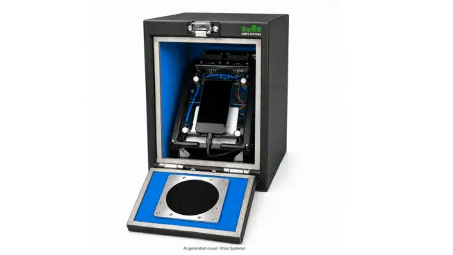
Modern wireless hardware is moving toward higher frequencies, tighter integration, and faster validation cycles. A small RF shielded box gives engineers a controlled electromagnetic environment around a device under test (DUT), helping separate actual device behavior from ambient interference.
As wireless components become more sophisticated, engineers need greater control over the test environment before moving from component validation to complete system testing. Even small sources of RF leakage, unwanted reflections, or inconsistent DUT positioning can influence measurements and make otherwise repeatable tests difficult to reproduce.
Key Takeaways
- Frequency range, isolation level, absorber design, and DUT geometry should all be defined before selecting an enclosure.
- Small or compact enclosures can support R&D, QA, and production validation across a range of programs.
- Interfaces and cables can become paths for unwanted RF coupling if not properly designed.
- Internal reflections can distort measurements even in well-shielded enclosures, which is why absorber treatment matters.
- Future-ready designs should account for expanding frequency bands and automation requirements.
Why Compact RF Control Matters
Open laboratories typically contain Wi-Fi, cellular signals, switching supplies, clocks, and other RF sources that can couple into a DUT and distort results.
A controlled enclosure limits external electromagnetic energy reaching the DUT while reducing unwanted radiation escaping from the test area. This makes it useful for component-level RF testing, receiver sensitivity measurements, emissions analysis, debugging, and repeatability studies.
The Details Engineers Commonly Miss
Frequency coverage is the first major consideration. Shielding that performs well at one band may behave differently at another. Engineers should examine the operating range, harmonics, and out-of-band interferers. An RF shielding box should be evaluated through measured attenuation across the required spectrum, rather than through a single headline specification.
One weak interface can limit total isolation. An RF isolation box needs precisely engineered contact surfaces, feedthroughs, and access mechanisms.
Internal reflections are another underappreciated source of measurement trouble. Conductive walls can reflect RF energy along different paths around the DUT, and in these cases absorber material becomes an important part of the design.
Why RF Validation Is Becoming More Demanding
The wider semiconductor and wireless-hardware ecosystem continues to expand, which places more pressure on validation environments to remain efficient and repeatable. As product cycles shorten and device counts grow, engineering teams face compressed validation timelines without room to compromise on measurement confidence.
A well-designed RF test box can provide a repeatable environment for component characterization before a design progresses into larger system-level testing.
The shielded test box should also be revalidated when fixtures, DUT geometry, or interfaces change. Multiple shielded test boxes can be deployed in parallel to support higher validation throughput as programs scale.
Interfaces Are Part of the RF Design
USB, Ethernet, DC, AC, optical, and RF connections can introduce conducted or radiated coupling when poorly integrated. Cable routing, filtering, and feedthrough design should match the required bandwidth.
This is where a robust electromagnetic shielding enclosure protects measurement integrity and repeatability. Mechanical repeatability matters as well, since DUT movement can change electrical results.
A compact RF shielded enclosure designed for production should support consistent loading, controlled access, and repeatable DUT positioning. Automation should also be considered early, because a modern RF testing enclosure may require RF, power, monitoring, communication, and test-management interfaces.
Designing Beyond Today’s Frequency Plan
Wireless platforms are progressing toward more complex multi-band and mmWave architectures. An RF isolation enclosure should therefore be assessed for frequency scalability rather than selected only around today’s nominal test band.
Conducted, radiated, emissions, sensitivity, and OTA measurements can also require different internal configurations. A compact RF shielded enclosure designed for one application may not suit another.
This engineering-led approach is reflected in companies such as Orbis Systems, where RF shielding solutions for wireless testing are developed with configurable interfaces and integration options for R&D and production environments.
Procurement teams comparing solutions should evaluate candidate enclosures using the same DUT and measurement criteria, so that specifications are judged on shielding performance rather than on physical size alone.
From Engineering Bench to Production
During development, a well-designed component-level test setup can support characterization and debugging. It can also be connected to and automated alongside other test equipment as the program matures.
A component testing setup that has been well thought through avoids the need for separate isolated setups for component and system-level testing, and makes it easier to accommodate later upgrades. Component-level RF testing can then continue without rebuilding the entire test environment.
For B2B engineering teams, the goal is not simply to block RF energy. It is to create a predictable measurement environment that scales with the product roadmap.
A Practical Engineering Checklist
Before specifying an enclosure, document the following:
- Frequency range, bandwidth, and target attenuation
- DUT dimensions, connectors, antenna orientation, and fixtures
- Absorber requirements and acceptable internal reflections
- RF, power, data, cooling, and control interfaces
- DUT loading method
- Calibration and shielding verification requirements
- Future frequency expansion
A systems-level approach that treats shielding as part of the measurement chain, combining enclosure engineering with interfaces and automation, can reduce redesign risk and support more consistent test data across program stages.
Where Better Test Control Leads
Future validation will combine isolation, automation, repeatability, and visibility. Treating shielding as part of the measurement chain can reduce uncertainty before system-level validation begins.
This structured approach is aligned with the direction taken by companies such as Orbis Systems, where RF testing solutions range from compact enclosures to larger OTA environments. Larger RF shielded enclosures can support growing DUTs and higher test volumes, while compact RF shielded enclosures continue to serve earlier development stages.
Frequently Asked Questions
1. What is a small RF shielded box used for?
A small RF shielded box provides a controlled electromagnetic environment for testing individual components, allowing engineers to obtain repeatable RF measurements without interference from the surrounding lab environment.
2. How much isolation does an RF isolation box need?
The required isolation depends on several factors, including operating frequency, ambient RF level, the sensitivity of the device under test, and the specific measurement objective. There is no single fixed value that suits every scenario.
3. Can a shielded test box support automated testing?
Yes. When properly designed, shielded test boxes can integrate RF, power, USB, Ethernet, optical, and control interfaces with the surrounding automated test equipment, allowing test sequences to run without repeated manual setup.
4. Why are absorbers used inside RF enclosures?
Absorbers help reduce internal reflections that would otherwise contaminate measurements. This supports cleaner test data, particularly at higher frequencies where reflection paths become more difficult to characterize.
5. Can one enclosure support future RF standards?
It can, when shielding performance, interfaces, absorber design, and frequency range are specified with sufficient engineering headroom to accommodate upcoming standards without requiring a full redesign.