Table of Contents
- Introduction to Modern RF Test Environments
- Understanding Custom Anechoic Chambers
- Core Anechoic Chamber Specifications
- Design Needs for mmWave Testing Chambers
- Integration with 5G OTA Testing Solutions
- Practical Design and Planning Guidelines
- Building Reliable Foundations for Advanced RF Testing
- Frequently Asked Questions
Introduction to Modern RF Test Environments
Wireless systems are moving quickly toward higher speeds and higher frequencies. As a result, engineers need test environments that can deliver stable and repeatable measurements. Custom chambers built around clear anechoic chamber specifications create a controlled space where radio signals behave in a predictable way. These chambers support accurate measurements for antennas, modules, and full devices that operate in advanced wireless bands.
At the same time, modern laboratories focus on Next-gen RF testing that supports both research and production. For this reason, chambers must also work with 5G OTA testing solutions and advanced mmWave testing chambers. A well-designed chamber removes reflections, blocks outside noise, and supports automation. Therefore, it becomes a central part of any professional RF test setup.
Key Takeaways
- Custom chambers are essential tools for accurate wireless testing
- Clear anechoic chamber specifications define performance and reliability.
- Specialized mmWave testing chambers address the challenges of high-frequency signals.
- Strong integration with 5G OTA testing solutions enables efficient automated workflows.
- Finally, structured planning and maintenance protect long-term measurement quality.
Understanding Custom Anechoic Chambers
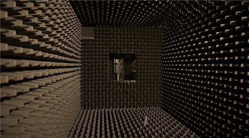
A custom anechoic chamber is a shielded enclosure designed to provide electromagnetic isolation from external interference while minimizing internal reflections. Structurally like advanced RF shielded rooms, it incorporates RF absorber materials on interior surfaces to reduce reflected energy and suppress multipath propagation. By lowering chamber reflectivity within a defined quiet zone, the system approximates free-space conditions for controlled RF measurements.
This controlled electromagnetic environment enables engineers to accurately measure antenna radiation patterns, gain, beam characteristics, and overall RF performance with minimal environmental distortion.
Custom anechoic chambers are engineered for specific frequency ranges and measurement objectives. Some designs are optimized for sub-6 GHz applications, where absorber depth and chamber dimensions must support longer wavelengths. Others are tailored for mm Wave operation, where shorter wavelengths demand tighter mechanical tolerances, specialized absorber materials, and enhanced surface precision.
When the chamber design aligns with the intended frequency band, device size, and test methodology, it supports reliable next-generation RF testing and provides a robust foundation for 5G OTA testing solutions. Careful definition of anechoic chamber specifications—including frequency range, shielding effectiveness, quiet zone performance, and mechanical stability—ensures consistent long-term measurement accuracy and repeatability.
Core Anechoic Chamber Specifications
Defining the right technical parameters is essential before construction begins. These parameters affect accuracy, repeatability, and long-term usability.
First, the frequency range and absorber performance must match the target bands. Absorbers should provide low reflectivity across sub-6 GHz and mm Wave frequencies. Proper absorber performance improves quiet zone quality and reduces internal signal reflections.
Second, chamber size and layout must support the required test distance. Adequate space is needed for antennas, fixtures, and device mounts. Proper spacing helps maintain valid measurement conditions.
Third, shielding effectiveness protects the chamber from outside interference. Doors, seams, and cable entries must maintain strong shielding across the operating band.
Fourth, access ports and cable feedthroughs should be placed carefully. They must allow instrument connections without disturbing the absorber field.
Finally, mechanical stability and environmental control support consistent results. Stable structures and controlled temperature conditions improve measurement reliability.
Design Needs for mmWave Testing Chambers
mmWave testing chambers require special attention because high frequencies behave differently from lower bands. Small surface gaps or uneven absorber placement can cause noticeable reflections. Therefore, absorber geometry must be precise and uniform.
Accurate alignment is also critical. Positioning systems must hold tight tolerances so that angular measurements remain correct. In addition, thermal stability is important because temperature variation can influence DUT RF performance, phase stability, and measurement repeatability
Material selection plays another role. Structural materials and surface finishes should minimize unintended scattering and reflection within the quiet zone. When these design factors are handled correctly, the chamber can meet demanding anechoic chamber specifications and support reliable mmWave measurements.
Integration with 5G OTA Testing Solutions
A chamber does not work alone. It must operate as part of a complete 5G OTA testing solution environment that supports modern automated test setups. Integration begins with automated positioners that move the device under test and antennas in a controlled way. Automation improves repeatability and reduces manual errors.
Test instruments such as network analyzers and signal sources connect through shielded feedthroughs.RF switching and routing hardware enable configurable measurement topologies for MIMO and beamforming validation.. In addition, software coordinates equipment control and test sequencing.
These automated systems create efficient workflows for 5G NR and future wireless validation. They allow laboratories to scale from development testing to higher volume validation. A chamber designed for integration can adapt to changing test needs while maintaining performance.
Practical Design and Planning Guidelines
Successful chamber projects follow clear engineering steps. Early definition of goals helps avoid costly redesign. Teams should agree on frequency coverage, device size, and expected throughput before final design.
Prototype validation can confirm absorber performance and layout choices. Regular calibration plans protect long-term accuracy. Designers should also allow room for upgrades so that the chamber can support future technologies.
Careful planning keeps the chamber aligned with the required anechoic chamber specifications and ensures steady performance throughout its service life.
Building Reliable Foundations for Advanced RF Testing
Modern wireless development depends on an electromagnetically controlled and repeatable measurement environment. Custom chambers built for 5G NR (FR1/FR2) and future wireless validation
Provide the controlled conditions needed for the accurate evaluation of advanced devices.
When engineers focus on absorber performance, shielding quality, and system integration, the resulting environment supports Repeatable and traceable measurement results
A carefully designed chamber becomes a lasting foundation for 5G and mmWave innovation.
Frequently Asked Questions
- What frequency coverage is typical for a chamber used in 5G and mmWave work?
A chamber for 5G and mmWave testing usually supports sub-6 GHz bands and extends into higher mmWave ranges such as 24 GHz to 40 GHz. The exact coverage depends on project goals and device requirements. Engineers choose absorber materials and shielding methods that maintain stable performance across this span. Broader coverage allows one chamber to support multiple test programs.
- How do absorber materials influence measurement accuracy?
Absorber materials reduce reflections inside the chamber. High-quality absorbers create a quieter environment and approximate free-space boundary conditions more closely. This improvement leads to more accurate antenna and signal measurements. Consistent absorber performance across the frequency range is important for repeatable results.
- Why is chamber size important for antenna testing?
Chamber size determines the available distance between antennas and the device under test. Adequate spacing is needed to achieve correct measurement conditions. For very large arrays or mm Wave systems, compact ranges or near-field scanning may also be used. Proper sizing supports valid far-field measurements and stable test geometry. - What role does automation play in modern RF chambers?
Automation controls positioners, instruments, and test sequences. It improves repeatability and reduces human error. Automated systems also increase test efficiency and support complex measurement routines. As a result, laboratories can handle higher workloads without sacrificing accuracy.
- How often should a chamber be checked or calibrated?
Regular inspection and calibration protect measurement quality. Many facilities perform checks every six to twelve months, depending on usage. Calibration verifies absorber condition and shielding performance. Scheduled maintenance helps ensure that the chamber continues to meet technical requirements.