We are creative, ambitious and ready for challenges!

Categories
Blogs Resources

Best Practices for Designing RF Switch Matrices in Modern Wireless Labs

Table of Contents

  1. Importance of RF Switch Matrix Design
  2. Key Points for High-Frequency Switching
  3. Selecting the Right Matrix Structure
  4. Power Handling and High-Power RF Switching
  5. Automation and Control Considerations
  6. Installation and Ongoing Validation
  7. Key Takeaways
  8. Frequently Asked Questions

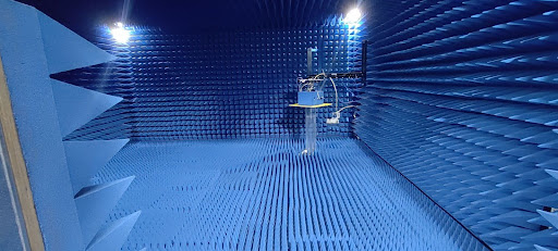
Wireless testing labs today are not simple places. Engineers work with many devices, many frequency ranges, and many test setups. Some tests focus on Sub-6 GHz. Others involve mmWave or OTA testing. Often, more than one device is tested at the same time.

In such conditions, signal routing must remain stable and repeatable. If signal paths change often, test results can change too. This creates confusion and wastes time.

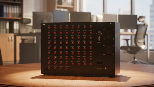
This is where an RF switch matrix becomes important. It allows RF signals to move between instruments and devices without constant cable changes. When done correctly, this improves repeatability and reduces physical handling of test equipment. This article explains how to design RF switch matrices for modern wireless labs in a clear and practical way.

Best Practices for Designing RF Switch Matrices in Modern Wireless Labs

Summary Highlights

  • A well-planned RF switch matrix improves test repeatability
  • High-frequency behaviour must be carefully checked
  • Modular structures support future lab growth
  • Stable RF test routing reduces manual errors
  • Automation and validation are essential for consistent results

Importance of RF Switch Matrix Design

Wireless testing has changed over the years. Earlier, labs worked with fewer bands and simpler devices. Today, the situation is very different. Multiple radios, antennas, and instruments are used together.

Because of this, RF test routing must be reliable. A well-designed RF switch matrix helps engineers keep test conditions the same across repeated measurements. This improves confidence in results.

Another benefit is reduced cable movement. Frequent manual reconnections can damage connectors over time. Centralized switching reduces this risk. Many labs that use modular switching platforms, including those from Orbis Systems, focus on improving test stability while keeping lab operations efficient.

Key Points for High-Frequency Switching

High-frequency testing requires extra attention. Small losses or reflections can affect measurements more than expected.

Engineers should focus on the following:

  • Insertion loss, which should stay as low as possible
  • Isolation, to avoid signal leakage between paths
  • Return loss and VSWR, which affect impedance matching
  • Switching speed, especially for automated testing

A high-frequency switch matrix must perform well across its full frequency range. Testing only at one frequency is not enough. Cable quality, connector type, and adapters also affect performance. Therefore, these parts must be considered as part of the overall RF path.

Selecting the Right Matrix Structure

The internal structure of a switch matrix affects how flexible the system will be in the future. Choosing the wrong structure can limit expansion.

Common structures include:

  • Blocking matrices, suitable for fixed and predictable routing
  • Non-blocking matrices, which allow several paths at the same time
  • Modular matrices, which can grow with changing lab needs

Scalability matters most in R&D and validation labs. New devices and new frequency bands are added regularly. Modular designs reduce the need for complete system changes later. This is one reason modular RF switching solutions from Orbis Systems are often considered for long-term lab setups.

Power Handling and High-Power RF Switching

Not all RF tests use low signal levels. Some tests involve transmitters, power amplifiers, or stress conditions. In these cases, power handling becomes critical.

Designers must review:

  • Continuous power limits
  • Peak power ratings
  • Heat build-up during repeated switching

Using switches beyond their limits can cause unstable readings or hardware damage. A properly rated high-power RF switch is required in such setups. Choosing the right high-power RF switch helps protect both the test system and the device under test.

Automation and Control Considerations

Manual switching is no longer practical in many labs. Automation improves speed and reduces mistakes.

When selecting switching systems, engineers should check:

  • Support for common control interfaces
  • Software-based control options
  • Compatibility with automated test systems

Automation ensures that switching paths remain the same every time a test runs. This improves repeatability. Many switching platforms from Orbis Systems are built to support automated environments while keeping system control straightforward.

Installation and Ongoing Validation

Design alone is not enough. Installation quality has a strong impact on performance.

Good practices include:

  • Avoiding sharp cable bends
  • Keeping cable lengths consistent where possible
  • Clearly marking signal paths
  • Performing regular performance checks

Validation should confirm that each RF path meets defined limits. Over time, cables and connectors can degrade. Regular checks help detect problems early and keep the RF switch matrix reliable.

Designing RF Switch Matrices for Reliable Lab Operation

Designing an RF switch matrix is not only about connecting signals. It is about ensuring stable, repeatable, and scalable testing. By focusing on structure, frequency performance, power handling, and automation, labs can build systems that support both current and future testing needs.

A careful and practical design approach helps wireless labs maintain accuracy and efficiency as technology continues to evolve.

Frequently Asked Questions

1. What does an RF switch matrix do in a wireless lab?

An RF switch matrix routes RF signals between instruments and devices without manual cable changes. This saves time and improves test consistency.

2. Why is high-frequency performance difficult to manage?

At higher frequencies, losses and reflections become more significant and sensitive to small variations. A high-frequency switch matrix is designed to control these effects and keep measurements stable.

3. When should a high-power RF switch be used?

A high-power RF switch should be used when testing involves strong RF signals, such as transmitter output testing or power stress tests.

4. How often should validation be performed?

Validation should be done after installation and repeated at regular intervals. This helps ensure long-term performance stability.

5. Can RF switch matrices support automated testing?

Yes. Modern switching systems, including those from Orbis Systems, are designed to work with automated test setups using software control.

Categories
Blogs Resources

How to Build a Future-Proof 5G/6G Testbed for the Next Decade

Table of Contents

  1. The Purpose of a 5G and 6G Testbed
  2. Basic Principles for a Long-Lasting Testbed
  3. Technical Capabilities Needed for the Next Decade
  4. Supporting Low Latency and High Reliability
  5. Cloud and Edge-Based Testing Environments
  6. Automation and Data Analysis
  7. Scaling from Research to Production
  8. Frequently Asked Questions

Wireless technology is changing faster than ever. While 5G is still being deployed, work on 6G has already started. New frequency ranges, new antenna designs, and new network models are becoming part of everyday engineering work. Because of this, testing environments must also evolve.

A testbed that works today may not be suitable in five or ten years. Many labs are now rethinking how their systems are designed. The goal is not only to test current devices but also to stay ready for future standards. Well-planned 6G testing solutions help engineers support today’s requirements while preparing for what comes next.

How to Build a Future-Proof 5G/6G Testbed for the Next Decade

Key Takeaways

  • Future-proof testbeds must support many frequency bands and radio technologies.
  • Automation and cloud integration are essential for long-term scalability.
  • Modular design protects investment and reduces upgrade costs.
  • Consistent testing methods help bridge research and production.
  • Orbis Systems focuses on building flexible test platforms for evolving wireless needs.

The Purpose of a 5G and 6G Testbed


A wireless testbed is a controlled setup where devices and networks are measured under known conditions. It allows engineers to check performance, find problems, and confirm that systems meet required standards. In next-generation wireless testing, the role of a testbed becomes even more important.

Modern testbed design for 6G must support many technologies at the same time. Devices often need to operate across different frequency bands and radio access technologies. As a result, test environments must be flexible and easy to adapt. This helps teams move smoothly from early research to final validation.

Basic Principles for a Long-Lasting Testbed

To remain useful over many years, a testbed must be designed with care. Some basic principles help ensure long-term value.

First, modular design is essential. Each part of the system should be easy to replace or upgrade. This allows changes without rebuilding everything.

Next, automation should be part of the design from the beginning. Automated tests reduce errors and save time. They also make results more consistent.

Finally, the testbed should follow industry standards closely. This helps ensure compatibility with future updates and new releases. Orbis Systems follows these principles when developing flexible test platforms.

Technical Capabilities Needed for the Next Decade

A future-ready testbed must support a wide range of technical features. These features allow reliable testing today and smooth expansion tomorrow. Strong 6G testing solutions are built around the following capabilities.

Multi-Band and Multi-RAT Support

  • Operation across sub-6 GHz, mmWave from 24 to 100 GHz, and future terahertz ranges.
  • Support for 5G NR, LTE, Wi-Fi, and emerging 6G waveforms

Massive MIMO and Beamforming

  • Testing of large antenna arrays with dynamic beam control
  • Measurement of spectral efficiency, spatial multiplexing, and interference behavior

High-Precision Channel Emulation

  • Simulation of urban, rural, indoor, and vehicular environments
  • Inclusion of mobility effects, fading, Doppler shifts, and interference conditions

Together, these features allow engineers to test devices in conditions that closely reflect real-world use.

Supporting Low Latency and High Reliability

Many new applications depend on fast and reliable communication. Examples include industrial control, autonomous transport, and vehicle-to-everything systems. Because of this, testbeds must support detailed latency and reliability testing.

Validation should include measurements of end-to-end delay, jitter, and packet loss. Tests must run under controlled load conditions so results can be compared accurately. This type of testing helps confirm that systems meet strict performance requirements before deployment.

Cloud and Edge-Based Testing Environments

Wireless networks are no longer fully centralized. Cloud platforms and edge computing now play a major role. For this reason, testbeds must support cloud-native and edge-based architectures.

These environments allow engineers to test network slicing, multi-access edge computing, and distributed processing models. In addition, they support new ways of managing networks using data-driven methods. This approach is becoming a standard part of next-generation wireless testing.

Automation and Data Analysis

Automation is now a basic requirement for modern testing. Manual testing takes time and often leads to inconsistent results. Automated workflows help reduce these problems.

Automation allows tests to run repeatedly under the same conditions. It also improves throughput in both lab and production environments. Data collected during testing can then be analyzed using advanced methods.

AI and machine learning tools help detect unusual behavior and performance trends. They also support better decision-making during development. These tools improve efficiency without changing the underlying test process.

Scaling from Research to Production

Many organizations struggle when moving from research testing to manufacturing validation. A future-ready testbed helps reduce this gap.

In research environments, flexibility and exploration are important. In production, repeatability and speed matter more. A well-designed testbed supports both needs using consistent measurement methods.

This approach shortens development cycles and improves product quality. Orbis Systems designs test platforms that support this transition from early testing to production-level validation.

Why Future-Ready Testbeds Matter

  • Faster innovation by supporting both 5G upgrades and early 6G research
  • More realistic validation through controlled and repeatable conditions
  • Long-term adaptability through modular and scalable design

These benefits support collaboration between manufacturers, operators, and research groups. Over time, this cooperation helps shape reliable next-generation wireless networks. Strong 6G testing solutions play a key role in this process.

Building Testbeds That Last

Wireless technology will continue to change over the next decade. Testing environments must be ready to change with it. A future-ready testbed supports today’s needs while remaining flexible for tomorrow.

By focusing on modular design, realistic testing, and automation, organizations can reduce risk and improve efficiency. With the right planning, testbeds can remain useful as standards evolve. Orbis Systems continues to support this approach by developing adaptable platforms for next-generation wireless testing.

Frequently Asked Questions

1. What makes a testbed ready for future 6G development?

A testbed is ready for 6G when it can be upgraded over time. It should support new frequency bands, antenna setups, and waveforms without replacing the full system. This allows continued testing as standards evolve.

2. Why is over-the-air (OTA) testing important for modern wireless systems?

OTA testing measures how devices perform in real air conditions. It is important because beamforming and antenna behavior cannot be fully tested using cables. OTA testing helps confirm real-world performance.

3. How does automation improve wireless testing?

Automation reduces manual work and errors. Tests run the same way each time, which improves accuracy and repeatability. It also saves time by allowing tests to run faster and in larger volumes.

4. Can one testbed be used for both research and production testing?

Yes. A flexible testbed can support early research and later production testing. Using the same test methods helps ensure consistent results across both stages.

5. How do 6G testing solutions support long-term planning?

They allow gradual upgrades instead of full system changes. This helps reduce cost and keeps test environments ready for future wireless technologies.


Categories
Blogs Resources

Custom RF Shield Room Design: Engineering for Your Specific Requirements

Table of Contents

  1. Key Takeaways
  2. Understanding the Purpose of RF Shield Rooms
  3. What Is an RF Shield Room
  4. RF Shield Room vs RF Shielded Box vs OTA Chamber
  5. Important Engineering Factors in RF Shield Room Design
  6. Who Needs a Custom RF Isolation Chamber
  7. A Complete Look at Custom RF Shield Room Planning
  8. Frequently Asked Questions

Understanding the Purpose of RF Shield Rooms

Wireless devices continue to improve and include more advanced technology. Because of this, testing environments must be stable and free from interference. If outside radio signals reach a device during testing, measurements may become inaccurate. As a result, engineers may not receive reliable results or may need to repeat testing.

A custom RF shield room or RF isolation chamber creates a clean and controlled space. This supports accurate performance testing and helps maintain consistent testing over time. As testing expands into areas like sub-6 GHz and mmWave, controlled test environments are now an essential part of device development and manufacturing.

Custom RF Shield Room Design: Engineering for Your Specific Requirements

Key Takeaways

  •  A custom RF shield room or RF isolation chamber provides a controlled electromagnetic environment by attenuating external RF interference and containing internally generated signals
  • RF shielded boxes are suitable for small DUTs and early-stage testing, while full RF shield rooms are better suited for larger systems, multi-DUT setups, and scalable long-term test requirements.
  • Key engineering considerations include shielding effectiveness, proper grounding for noise control and safety, filtered power and signal interfaces, and well-planned environmental infrastructure.
  • A properly engineered RF isolation chamber enables repeatable and reliable measurements for 5G, IoT, and emerging wireless technologies, including higher-frequency applications.
  • Custom RF shield room designs offer flexibility and future readiness as test standards and frequency requirements evolve.

What Is an RF Shield Room

An RF shield room is a specially designed, enclosed space used to block radio frequency (RF) signals from entering or leaving the area. It creates a controlled electromagnetic environment so that wireless devices can be tested without interference from external signals or leakage from internal sources.

RF shield rooms are constructed using conductive materials such as steel, copper, or aluminum panels. They incorporate RF-tight doors, sealed joints, filtered power and signal feedthroughs, and shielded ventilation to maintain high shielding effectiveness across the required frequency range.

For smaller testing tasks, an RF shielded box may be the right choice. Orbis Systems offers RF shielded box solutions suitable for smaller DUTs. These can support accurate testing in a limited space or during early development phases.

RF Shield Room vs RF Shielded Box vs OTA Chamber

Choosing between these options depends on the product size, testing goals, and long-term needs.

Requirement RF Shielded Box RF Shield Room or RF Isolation Chamber OTA or Anechoic Chamber
Small DUT testing Suitable Possible but not necessary Not needed
Multi-DUT or extensive DUT testing Limited Suitable Suitable
Throughput and antenna testing Limited Suitable with absorbers Ideal
High frequency or mmWave testing Limited Suitable Suitable
Long-term growth or scalability Limited Suitable Suitable

An RF shielded box is helpful for compact devices. A complete RF shield room is better for larger equipment and environments where future testing may increase. For antenna performance testing, an OTA chamber may be required.

Important Engineering Factors in RF Shield Room Design

Several engineering elements help ensure a reliable RF shield room.

Shielding Integrity and Material Quality

The room needs proper shielding panels, sealed access points, and a continuous conductive structure. Every seam, connection, or entry must maintain shielding performance.

Filtered Access and Connectivity

Power lines, communication lines, and ventilation should use filtered paths. This protects the shielding performance while allowing the room to operate as a working test area.

Grounding

Grounding is essential for safety and noise control. A properly designed grounding scheme helps minimize conducted interference and supports stable and repeatable RF measurements

Environmental Planning

HVAC, lighting, and cable routing must be planned from the start. This ensures the room remains functional and avoids interference or performance loss.

Modularity

A modular RF shield room supports expansion. This helps engineers adjust the room if testing needs increase.

Frequency Compatibility

The shielding must support the tested frequency range. This includes sub-6 GHz, 5G, and mmWave signals.

Who Needs a Custom RF Isolation Chamber

Custom RF shield rooms are suitable for many environments, such as:

  • Research labs working with wireless product development
  • Consumer electronics and IoT device manufacturers
  • Telecom companies testing 5G and network hardware
  • Automotive and aerospace companies are testing communication systems
  • Defence and government testing environments
  • Production lines running multi-DUT automated testing

In these environments, consistent and repeatable results are significant. A custom enclosure helps achieve those results.

A Complete Look at Custom RF Shield Room Planning

A custom RF shield room is a long-term testing solution. It helps ensure controlled RF isolation and protects test accuracy. As devices grow in capability, the need for reliable testing conditions also increases.

Choosing between an RF shielded box, an RF shield room, or an OTA chamber depends on the type of testing, device size, and long-term plan. A custom RF isolation chamber supports flexibility and repeatable results for both current and future wireless testing.

This is especially important for advanced wireless technologies such as 5G, mm Wave, and future standards that require strict control of the RF environment

Frequently Asked Questions

1. What Is the Necessity of Putting a Shield Between a Test and Its Environment for RF Testing?

To avoid measuring results that have been compromised by outside sources, RF tests need to be conducted in an isolated environment. Testing inside an enclosed area (RF shield room) will also help to ensure that the test signals being used will not interfere with any other devices or communication systems in the immediate area.

2 What are the limitations and advantages of using an RF Shielded Box?

When testing small devices, an RF shielded box is suitable as it does not require a fully enclosed room for testing. This can also be helpful during early testing stages of the research and development process of a product, when more limited scenarios of use will be under investigation.

3 Can a custom RF Shield Room be used for 5G and mmWave testing?

Yes, a custom RF shield room can support testing at 5G and mmWave frequencies; however, to achieve accurate results at these frequencies, the custom RF shield room must be designed and constructed using the appropriate materials, design elements, and placements of absorbers.

4 Do Proper Grounding and Shielding Affect RF Shield Room Performance?

Yes. Proper grounding is essential for safety and for minimizing conducted electrical noise. While grounding does not directly improve RF shielding effectiveness, an improper grounding scheme can introduce noise and stability issues that affect measurement repeatability and overall test reliability.

5. Can a custom RF shield room be modified or expanded in the future

Yes. If the room is built using a modular design, it can be expanded or reconfigured. This helps align the testing environment with future products or new testing requirements.