Modern wireless products must perform reliably across multiple frequencies, signal paths, and operating conditions. As test setup complexity grows, manual switching between instrument connections becomes increasingly difficult to manage. It slows down product validation, introduces configuration errors, and adds test variation that makes results harder to reproduce. Integrating Signal Switching Units (SSUs) into a software-controlled test environment offers a more consistent approach.
For engineering teams, the goal is not simply to switch signals remotely. It is to coordinate instruments, routing configurations, measurement sequences, and test results within a single workflow. A well-designed RF test automation architecture helps organizations scale validation without turning every additional test path into a source of operational complexity.
Key Takeaways
- Software-controlled switching reduces the need for manual operation during complex test sequences.
- Test systems that integrate SSUs bring instrument control, signal routing, and measurement execution into one coordinated architecture.
- Consistent automation requires attention to switching specification, timing control, error handling, and result traceability.
- Modular design supports test system expansion as product specifications change.
- Future-ready test environments depend on software interfaces that support integration, diagnostics, and repeatable execution.
- Clear separation between routing logic and measurement logic makes the overall system easier to maintain.
Why RF Switching Needs a Software-Driven Approach
Traditional test benches often rely on engineers to reconnect cables, select instrument ports, and configure measurements for each test scenario. This approach can work for small systems, but it becomes difficult to manage with devices that operate across multiple bands, use several antenna paths, or require many measurement combinations.
Automated RF testing replaces many of these manual steps with programmed sequences. The software selects a routing configuration, establishes the required instrument settings, initiates measurements, and records the resulting data. Engineers can then execute the same sequence repeatedly under controlled conditions.
The wider shift toward coordinated, automated workflows across industrial environments reflects a similar need in RF laboratories. The practical opportunity is to reduce avoidable manual work while maintaining measurement integrity, especially as devices and test matrices grow more complex.
Understanding the Role of Signal Switching Units
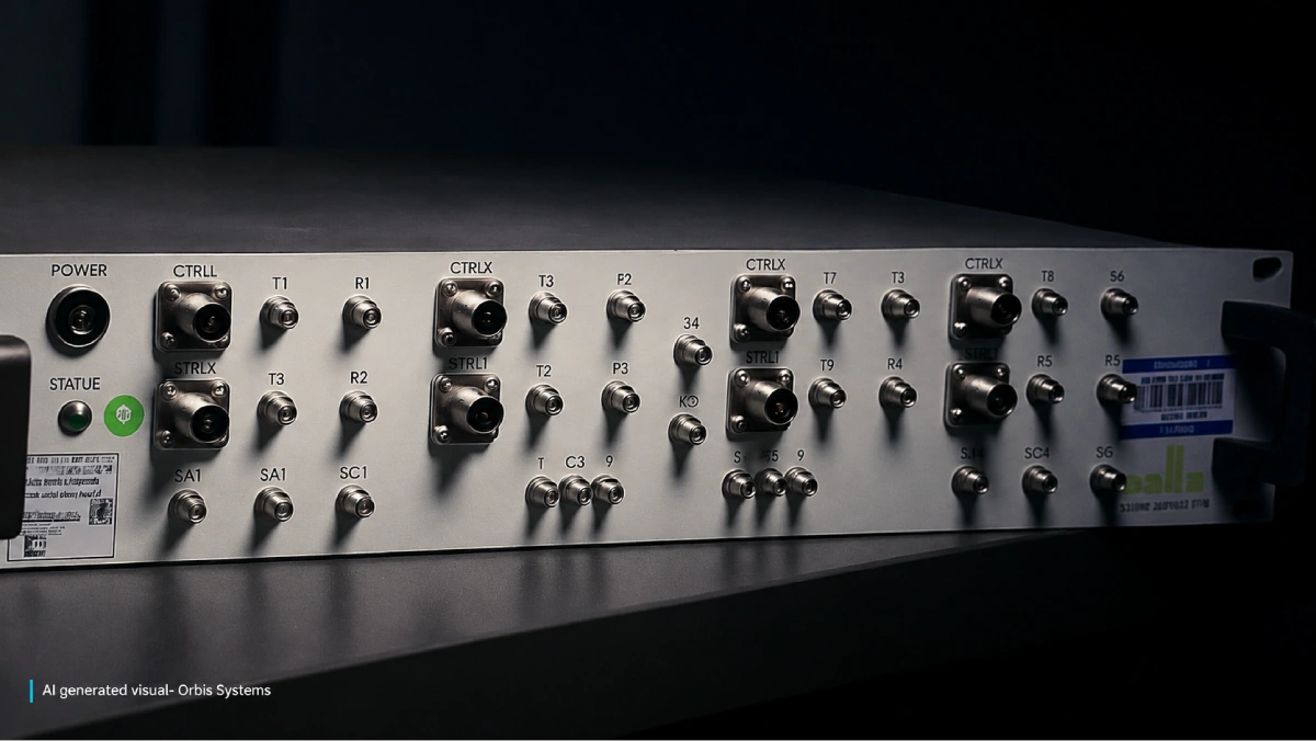
SSUs route signals between instruments, devices under test, antennas, loads, and other components. Depending on the application, the hardware may use electromechanical relays, solid-state switching technologies, or a combination of both.
The appropriate configuration depends on operating frequency, insertion loss, isolation, power handling, switching speed, and expected service life. Engineers also need to consider impedance matching and connector performance, since the switching hardware becomes part of the measurement path.
Integrating RF switches into the test architecture allows the controller to select predefined signal paths instead of relying on manual re connection. This becomes especially valuable when several instruments must access multiple ports, or when a test sequence requires repeated changes between transmit and receive paths.
An RF switch matrix can meet these routing requirements while keeping the physical setup organized. However, the routing design should also prevent prohibited connections, respect port availability, and stay within the electrical limits of each component.
Connecting SSUs to Test Automation Software
A successful integration requires a clear division of responsibilities between the hardware controller and the test application. The application manages test logic, while the switching controller executes routing commands and reports the resulting state.
A typical workflow includes four stages:
- Initialize the hardware. Establish the communication link with the switching controller and confirm that the connected measurement instruments are available.
- Configure the route. Select the required signal path using a predefined routing table or configuration profile.
- Synchronize measurements. Trigger acquisition only once the switching and instrument configuration is confirmed complete.
- Capture and validate results. Save the measured values along with routing state, instrument settings, and test metadata.
Test automation software should provide a clear, well documented way to initiate actions, validate results, and handle anomalies. Integrations can be built through vendor APIs, instrument command sets, drivers, or communication protocols supported by the platform.
A practical implementation also needs timeout management, command validation, and recovery procedures. If a switching operation fails, the software should halt the affected measurement sequence rather than assume that the requested path is active.
Designing a Reliable Switching Architecture
The physical and software layers must work together. Even a sophisticated application cannot compensate for unsuitable switching hardware or a poorly planned signal path.
Engineers should evaluate the following factors before deployment:
- Electrical performance. Beyond standard parameters such as frequency coverage, insertion loss, isolation, return loss, and power limits, consider how these behave under different operating conditions.
- Timing behaviour. Measure switching and settling times under real conditions and set an appropriate delay before data acquisition begins.
- Route validation. Confirm that each programmed connection matches the approved test configuration.
- Fault management. Define what should happen when a loss of communication, relay failure, invalid command, or instrument error occurs.
- Scalability. Choose modular, configurable routing hardware so that new channels or additional instruments can be integrated without redesigning the system.
In larger setups, the RF switch matrix control layer should remain separate from individual test procedures wherever practical. This separation allows engineers to update measurement sequences without rewriting the entire routing layer.
It also makes it easier to reuse validated configurations across different products and development stages.
Making Automated RF Testing Repeatable and Traceable
Automation delivers its greatest value when results are consistent and explainable. Every measurement should correspond to a known hardware configuration, a verified route, and a defined instrument state.
A useful implementation records timestamps, route selections, instrument parameters, error messages, and measurement outputs. Where timing affects accuracy, the software should distinguish between command completion and measurement readiness. A relay may have changed state even though the signal path has not yet settled enough for a valid reading.
Teams should validate the complete sequence under realistic operating conditions before moving it into production. Regression testing can then confirm whether changes in software, hardware, or routing affect previously established measurements.
This engineering led approach is reflected in companies such as Orbis Systems, where coordinated hardware and software design supports demanding wireless validation workflows. For organizations developing more complex test environments, the objective is to build an architecture that remains manageable as measurement requirements expand.
Preparing RF Test Systems for Future Requirements
Wireless validation continues to evolve as devices incorporate more bands, more antennas, and increasingly demanding performance requirements. Test systems need to keep pace with these changes without creating fragile dependencies between hardware level code and application level logic.
A modular approach to RF test equipment helps teams introduce additional instruments, routes, or test cases with less disruption. Standardized interfaces, configuration driven routing, and consistent diagnostics also make systems easier to maintain over their operational life.
RF test automation should therefore be treated as an architectural decision rather than a late software feature. Planning for expansion, observability, and fault recovery from the beginning gives engineering teams greater flexibility when requirements change.
Building a More Adaptable Validation Workflow
The next generation of RF laboratories will depend on more than faster instruments. It will require coordinated systems in which routing decisions, measurement execution, and result management operate as parts of one dependable workflow.
Integrating SSUs with well architected software allows engineering teams to reduce manual involvement, improve reusability, and expand test coverage while keeping signal quality under control. With the right hardware selection, validated switching procedures, and comprehensive error handling, automated test environments can adapt more smoothly as wireless standards evolve.
This structured approach is aligned with the direction taken by companies such as Orbis Systems, where RF testing and test system engineering capabilities are developed around the frequency range, switching topology, instrument ecosystem, throughput targets, and level of integration each program requires.
Frequently Asked Questions
1. What is a Signal Switching Unit in an RF test system?
A Signal Switching Unit routes signals between instruments, devices under test, antennas, and other test components. It removes the need to manually reconnect cables when the signal path changes, since those changes are handled through software instead.
2. How does software controlled RF switching improve testing?
Software controlled switching removes manual configuration work and allows the same route to be selected repeatedly with exactly the same configuration. It also supports centralized data logging, automated error detection, and synchronized instrument control.
3. What should engineers consider when selecting RF switches?
Important factors include frequency range, power handling, insertion loss, isolation, switching time, and long term reliability. The selected switches should cover the electrical and operational requirements of the test design.
4. Can an RF switch matrix work with existing test software?
Yes, provided the controller or application supports compatible interfaces, commands, or drivers. Integration testing is still needed to verify routing correctness, timing, and error handling under realistic test conditions.
5. Why is synchronization important in RF test automation?
A measurement taken before switching and signal settling are complete may be unreliable. Synchronization ensures that acquisition only begins once the intended route and instrument states are confirmed ready.